Portable multifunctional medical imaging matching system and method

A medical imaging, multi-functional technology, applied in medical science, sensors, diagnosis, etc., can solve problems such as large size, inability to remind medical staff, and inability to protect imaging equipment.

Pending Publication Date: 2022-01-11
高榕
View PDF0 Cites 0 Cited by
  • Summary
  • Abstract
  • Description
  • Claims
  • Application Information

AI Technical Summary

Problems solved by technology

[0004] The purpose of the present invention is to solve the shortcomings of the prior art that the volume is large and difficult to move, the imaging equipment cannot be protected, and the medical staff cannot be reminded to change shifts in time, and a portable multifunctional medical imaging supporting system with a compact structure is proposed. method

Method used


Image

  • Portable multifunctional medical imaging matching system and method
  • Portable multifunctional medical imaging matching system and method
  • Portable multifunctional medical imaging matching system and method

Examples


Embodiment 1

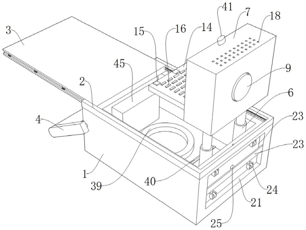
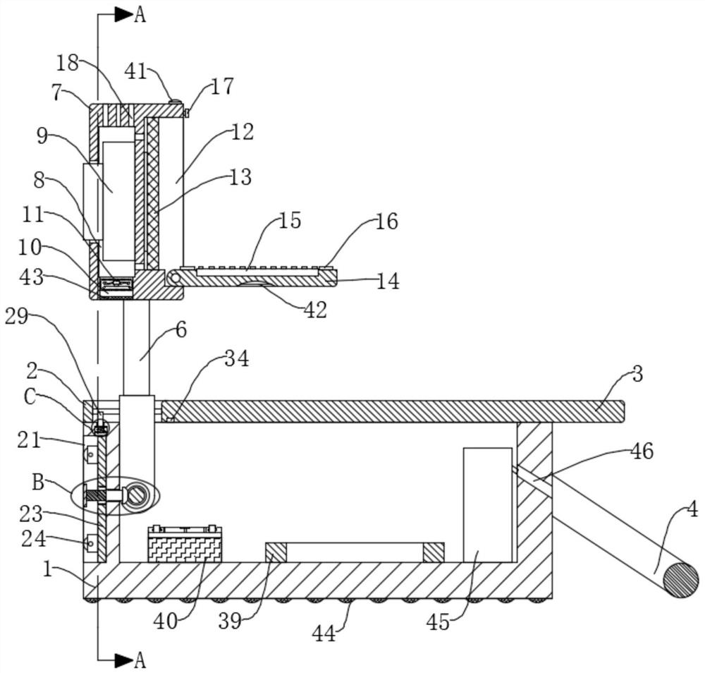
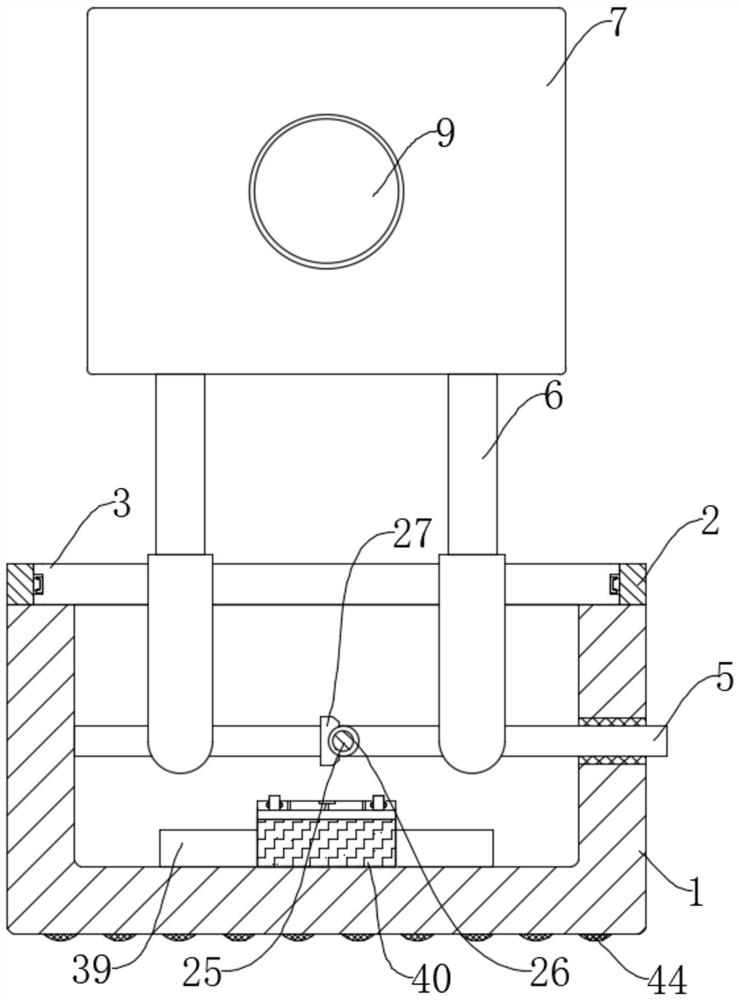
[0040] refer to Figure 1-9 , a portable multifunctional medical imaging supporting system, comprising a mobile box 1, a U-shaped plate 2 is fixedly connected to the top of the mobile box 1 by bolts, a cover plate 3 is slidably connected to the inside of the U-shaped plate 2, and a part of the mobile box 1 is far away from each other. The same rotating push rod 4 is connected to the side rotation, and the rotating rod 5 is connected to the moving box 1, and one end of the rotating rod 5 extends to one side of the moving box 1, and the outer wall of the rotating rod 5 is fixedly provided with two symmetrical The electric push rod 6, the sliding rods of the two electric push rods 6 are fixedly connected with the same scanning box 7 by bolts, the scanning box 7 is equipped with imaging components, and the bottom inner wall of the moving box 1 is fixedly connected with a circular rubber layer by bolts 39 and accumulator 40, the first chute 21 is provided on the side away from the ...

Embodiment 2

[0047] refer to Figure 1-10 , a portable multifunctional medical imaging supporting system, comprising a mobile box 1, a U-shaped plate 2 is fixedly connected to the top of the mobile box 1 by bolts, a cover plate 3 is slidably connected to the inside of the U-shaped plate 2, and a part of the mobile box 1 is far away from each other. The same rotating push rod 4 is connected to the side rotation, and the rotating rod 5 is connected to the moving box 1, and one end of the rotating rod 5 extends to one side of the moving box 1, and the outer wall of the rotating rod 5 is fixedly provided with two symmetrical The electric push rod 6, the sliding rods of the two electric push rods 6 are fixedly connected with the same scanning box 7 by bolts, the scanning box 7 is equipped with imaging components, and the bottom inner wall of the moving box 1 is fixedly connected with a circular rubber layer by bolts 39 and accumulator 40, the first chute 21 is provided on the side away from the...


PUM


Abstract

The invention discloses a portable multifunctional medical imaging matching system and method, and provides the following scheme that the portable multifunctional medical imaging matching system comprises a moving box. The top of the moving box is fixedly connected with a U-shaped plate, a cover plate is slidably connected in the U-shaped plate, and the sides, far away from each other, of the moving box are rotatably connected with the same rotating push rod; a rotating rod is rotationally connected into the moving box; and one end of the rotating rod extends to one side of the moving box, and the outer wall of the rotating rod is fixedly sleeved with two symmetrical electric push rods. An operating keyboard and a display screen can be protected by rotating the rotating plate and a protective cotton pad into a groove, in addition, a scanning box can be rotated into the moving box by rotating the rotating rod, and a scanner, the display screen and the operating keyboard are further protected and are prevented from being damaged by external force factors; and in addition, the rotating rod can drive the sliding plate to slide while rotating, and the moving box is convenient to carry.

Description

technical field [0001] The invention relates to the technical field of medical imaging equipment, in particular to a portable multifunctional medical imaging supporting system and method. Background technique [0002] With the growing interest in healthcare, active research into medical imaging devices is underway. As examples of medical imaging apparatuses, there may be ultrasonic imaging apparatuses, X-ray imaging apparatuses, computed tomography (CT) apparatuses, positron emission tomography (PET) apparatuses, magnetic resonance imaging (MRI) apparatuses, etc. X-ray imaging apparatuses are A device that obtains an image of the interior of a subject by irradiating X-rays to the subject and detecting the X-rays transmitted through the subject. A CT apparatus obtains images of the subject by passing X-rays through the subject at different angles tomographic image. A PET device is a device that generates tomographic images by injecting positron-emitting radionuclides into a...

Claims


Application Information

Patent Timeline
Patent Type & Authority Applications(China)
IPC IPC(8): A61B6/00A61B8/00A61B5/055A61B6/03
CPCA61B6/00A61B6/035A61B6/44A61B6/4405A61B6/461A61B5/055A61B8/00A61B8/44A61B8/4405A61B8/4427A61B8/461
Inventor 高榕
Owner 高榕
Why Eureka
Try Eureka