
Recovery system for electroplating liquid in electroplating bath

A recovery system and electroplating tank technology, applied in the electrolysis process, electrolysis components, cells, etc., can solve the problems of accelerating the cooling speed of the electroplating solution, consuming manpower, troublesome operation, etc., and achieve the effects of saving manpower, improving cleaning efficiency, and easy operation

Pending Publication Date: 2022-01-04
朱景
View PDF1 Cites 0 Cited by
  • Summary
  • Abstract
  • Description
  • Claims
  • Application Information

AI Technical Summary

Problems solved by technology

[0005] Although the above-mentioned device can drive the fan blades to rotate by setting the drive mechanism, the wind blown by the fan blades can blow and cool the electroplating solution in stirring through the exhaust pipe, thereby accelerating the cooling speed of the electroplating solution and improving the work of the operator. efficiency, in addition, the above-mentioned device also filters the electroplating solution by setting a filter screen to remove the waste residue in the electroplating solution, and prevents the filter screen from clogging by setting the rod against the filter screen to shake the filter screen, however, the filter screen is in the After using it for a period of time, it needs to be cleaned. The rod can only shake the filter screen, but cannot discharge the waste residue accumulated on the surface of the filter screen. Nowadays, the filter screen is generally disassembled and cleaned manually, but manual cleaning is labor-intensive and difficult to operate. Troublesome and inefficient to clean

Method used


Image

  • Recovery system for electroplating liquid in electroplating bath
  • Recovery system for electroplating liquid in electroplating bath
  • Recovery system for electroplating liquid in electroplating bath

Examples


Embodiment Construction

[0030] The following will clearly and completely describe the technical solutions in the embodiments of the present invention with reference to the accompanying drawings in the embodiments of the present invention. Obviously, the described embodiments are only some, not all, embodiments of the present invention. Based on the embodiments of the present invention, all other embodiments obtained by persons of ordinary skill in the art without making creative efforts belong to the protection scope of the present invention.

[0031] In describing the present invention, it is to be understood that the terms "center", "longitudinal", "transverse", "length", "width", "thickness", "upper", "lower", "front", " Back", "Left", "Right", "Straight", "Horizontal", "Top", "Bottom", "Inner", "Outer", "Clockwise", "Counterclockwise", etc. or The positional relationship is based on the orientation or positional relationship shown in the drawings, which is only for the convenience of describing t...


PUM


Abstract

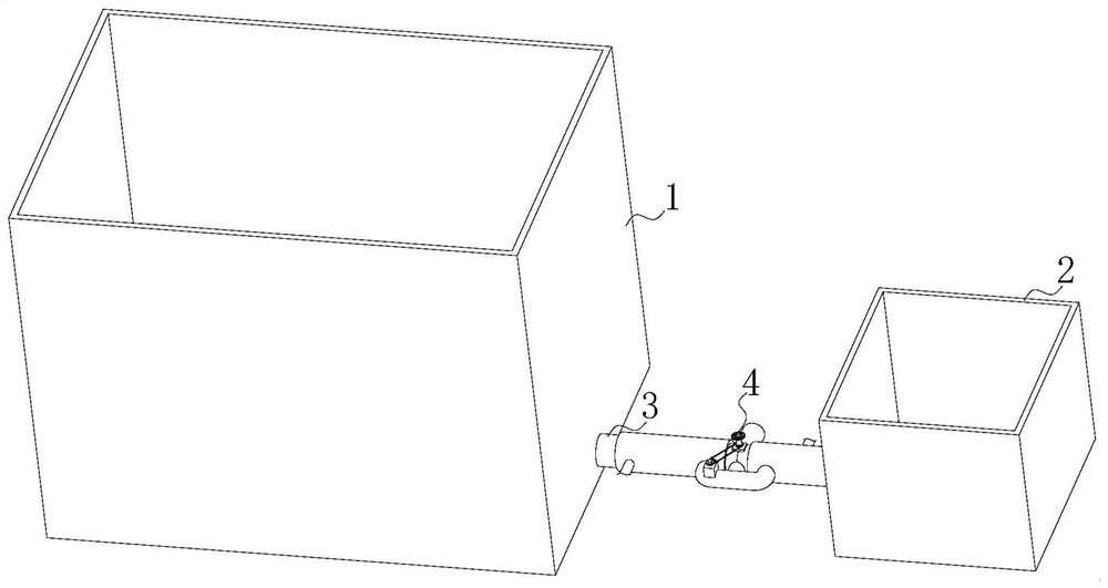
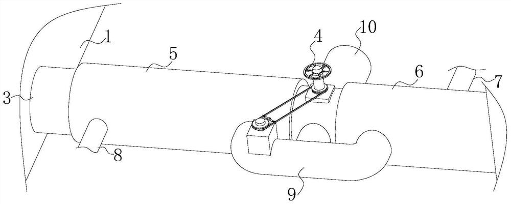
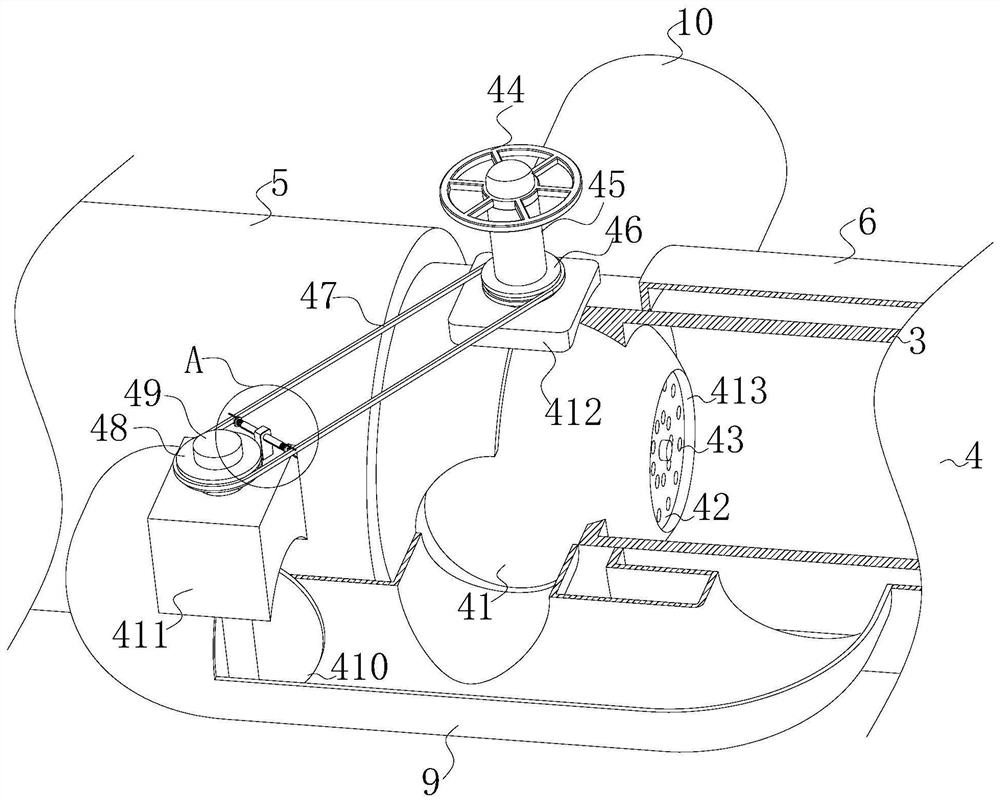
The invention relates to the technical field of electroplating liquid, in particular to a recovery system for electroplating liquid in an electroplating bath. The recovery system comprises the electroplating bath, a recovery tank and a connecting pipe, the right side of the outer surface of the electroplating bath is fixedly connected with the connecting pipe in a penetrating manner, and the end, far away from the electroplating bath, of the connecting pipe is fixedly connected with the recovery tank in a penetrating manner; a first cooling pipe and a second cooling pipe symmetrically and fixedly sleeve the two sides of the outer surface of the connecting pipe, a water outlet pipe is fixedly connected to the side, close to the electroplating bath, of the outer surface of the first cooling pipe in a penetrating mode, and a water inlet pipe is fixedly connected to the side, close to the recovery tank, of the outer surface of the second cooling pipe in a penetrating mode; and the side, away from the connecting pipe, of the outer surface of the first cooling pipe is fixedly connected with a U-shaped pipe in a penetrating mode, and the end, away from the first cooling pipe, of the U-shaped pipe is fixedly connected with the second cooling pipe in a penetrating mode. A filter screen does not need to be manually detached or manually cleaned, the filter screen can be cleaned in time, residues accumulated on the surface of the filter screen are discharge, the operation is easy and convenient, manpower is saved, and the cleaning efficiency is improved.

Description

technical field [0001] The invention relates to the technical field of electroplating solution, in particular to a recovery system for electroplating solution in an electroplating bath. Background technique [0002] The electroplating tank is used to install the solution for zinc plating, copper plating, nickel plating, gold plating, etc. The cathode moving electroplating tank is composed of a steel tank lined with soft polyvinyl chloride plastic, a conductive device, a steam heating tube and a cathode moving device. Electroplating solution refers to a liquid that can expand the cathodic current density range of the metal, improve the appearance of the coating, and increase the stability of the solution against oxidation. [0003] However, the temperature of the electroplating solution in the traditional electroplating tank is generally high during the process of electroplating the product, and then the operator needs to wait for the temperature of the solution to drop befo...

Claims


Application Information

Patent Timeline
Patent Type & Authority Applications(China)
IPC IPC(8): C25D21/18C25D21/06
CPCC25D21/18C25D21/06
Inventor 朱景张凡
Owner 朱景
Learn More