A controllable pressure manipulator end effector with polishing manipulator

A technology of end effector and public rotation, which is applied in the direction of grinding/polishing equipment, abrasive belt grinder, grinding machine tool parts, etc., can solve the problems such as the limitation of surface curvature radius, and achieve the prevention of interference phenomenon, large bearing capacity, and realization of The effect of elastic recoil

Active Publication Date: 2022-08-05
HARBIN INST OF TECH
View PDF4 Cites 0 Cited by
  • Summary
  • Abstract
  • Description
  • Claims
  • Application Information

AI Technical Summary

Problems solved by technology

At present, there are many methods for polishing complex optical components, such as magnetorheological polishing, water jet polishing, airbag polishing, ion beam polishing, laser polishing, etc., but most of the existing controllable contact pressure polishing tools are limited by the surface curvature radius of optical components. It is difficult to apply to complex optical surface polishing with large changes in surface curvature radius

Method used


Image

  • A controllable pressure manipulator end effector with polishing manipulator
  • A controllable pressure manipulator end effector with polishing manipulator
  • A controllable pressure manipulator end effector with polishing manipulator

Examples


Embodiment Construction

[0050] It should be noted that the embodiments of the present invention and the features of the embodiments may be combined with each other under the condition of no conflict.

[0051] The present invention will be described in detail below with reference to the accompanying drawings and in conjunction with the embodiments.

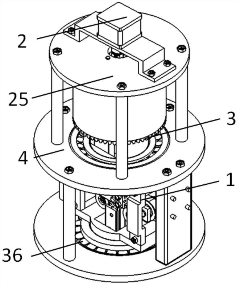
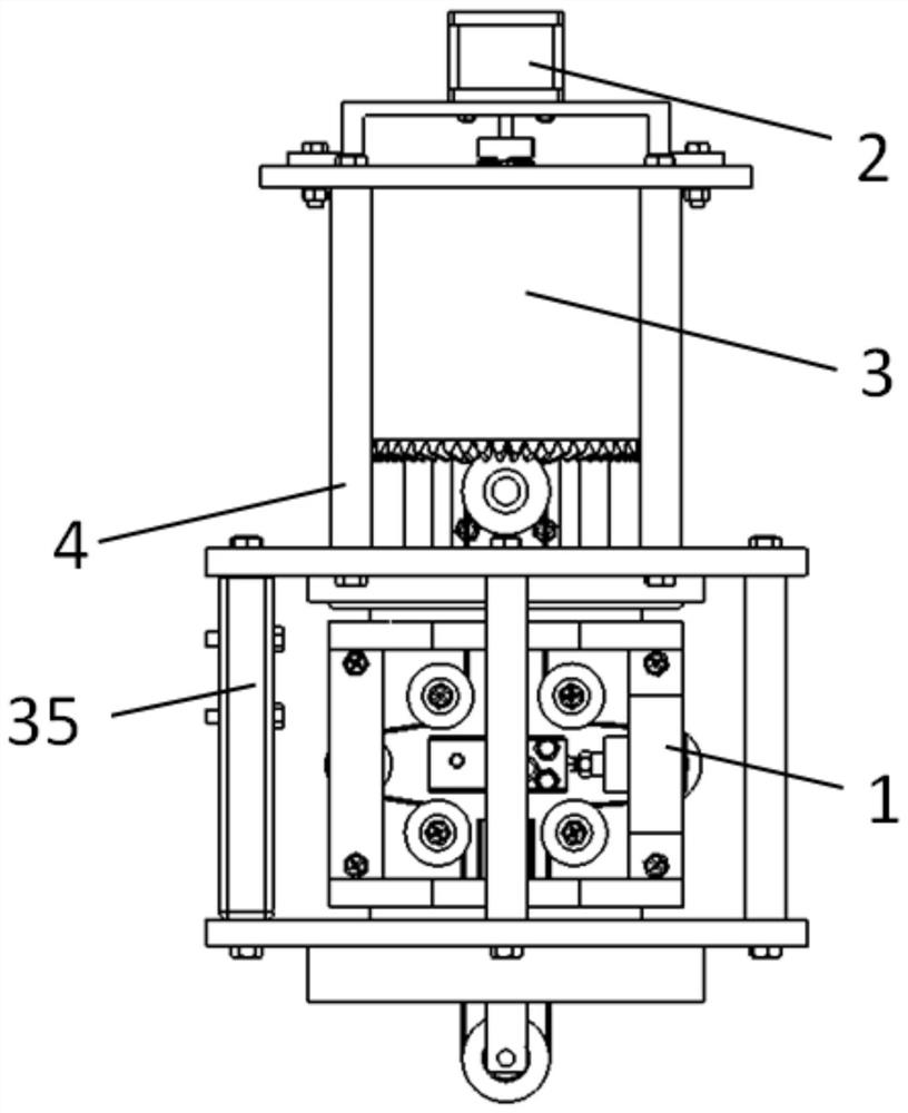
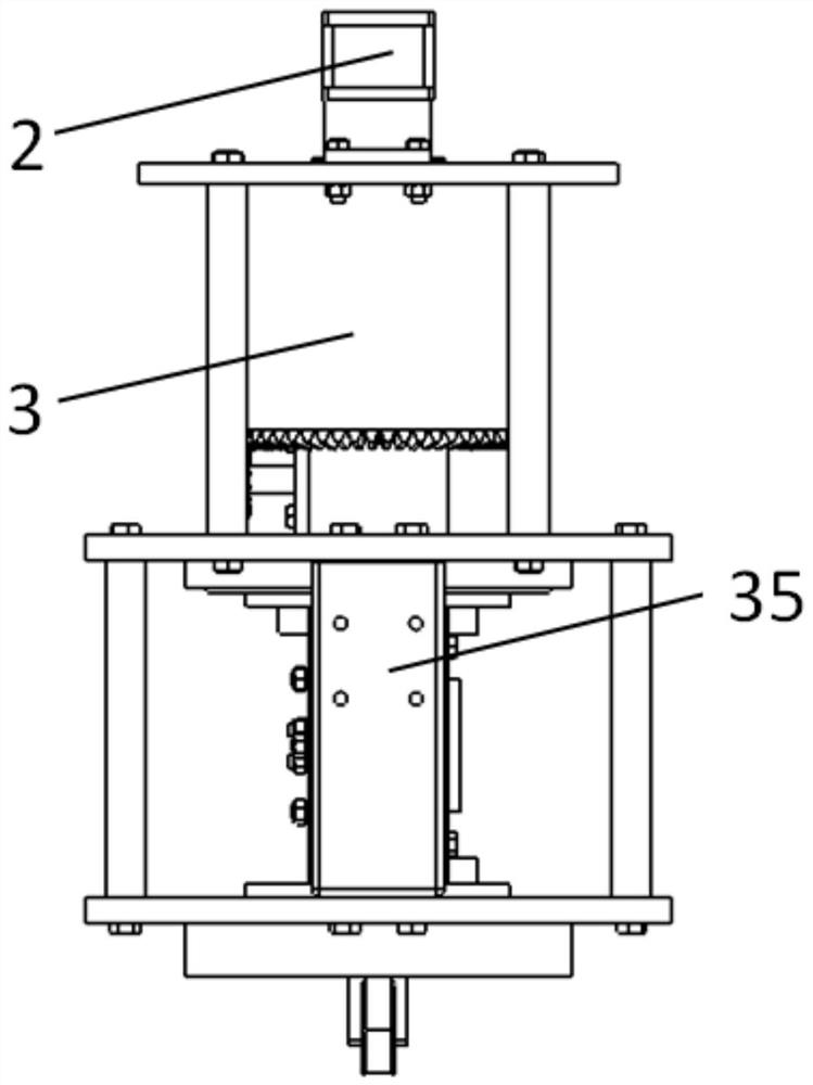
[0052] like Figure 1-Figure 25 As shown in the figure, a controllable pressure manipulator belt polishing manipulator end effector includes a belt polishing assembly 1, a motor drive assembly 2, a pneumatic rotation assembly 3, a supporting assembly 4, a tensioning assembly 6, and a polishing belt 11. and a number of adjustable guide idlers 9, the upper and lower ends of the belt polishing assembly 1 are respectively supported and installed on the support assembly 4 through a tapered roller bearing 36, and the pneumatic rotation assembly 3 is fixed on the top of the support assembly 4, so The pneumatic rotating assembly 3 is arranged above the belt poli...


PUM


Abstract

The present invention provides a controllable pressure manipulator belt polishing manipulator end effector, comprising a wheel belt polishing component, a motor driving component, a pneumatic rotating component, a supporting component, a tensioning component, a polishing belt and several adjustable types The guide idler, the upper and lower ends of the belt polishing assembly are respectively installed on the supporting assembly through a tapered roller bearing, the pneumatic rotating assembly is fixed on the top of the supporting assembly, the pneumatic rotating assembly is arranged above the belt polishing assembly, and the tensioning assembly and a number of guide idlers are installed in the belt polishing assembly, and the polishing belt is respectively set in tension with the tensioning part of the pneumatic rotating assembly, the tensioning end of the tensioning assembly, the tensioning part of the belt polishing assembly and each guide idler The motor driving component is arranged on the upper end of the pneumatic rotating component, the motor driving component drives the wheel belt polishing component to revolve, and the wheel belt polishing component cooperates with the pneumatic rotating component to make the polishing belt move. The invention realizes high-efficiency polishing of various optically hard and brittle materials and various precision requirements.

Description

technical field [0001] The invention belongs to the technical field of optical processing, and in particular relates to a pressure-controllable male rotation wheel belt polishing mechanical arm end effector. Background technique [0002] In the complex surface processing technology in the field of precision optical processing, it is necessary to polish the optical surface after milling to reduce workpiece damage and workpiece surface roughness, and improve the surface shape accuracy and surface quality of the workpiece to meet the actual use. Require. At present, there are many methods for polishing complex optical components, such as magnetorheological polishing, water jet polishing, airbag polishing, ion beam polishing, laser polishing, etc., but most of the existing controllable contact pressure polishing tools are affected by the surface curvature radius of the optical element. Due to limitations, it is difficult to apply to complex optical surface polishing with large ...

Claims


Application Information

Patent Timeline
Patent Type & Authority Patents(China)
IPC IPC(8): B24B21/12B24B21/00B24B21/18B24B21/20B24B47/12B24B41/00
CPCB24B21/12B24B21/006B24B21/18B24B21/20B24B47/12B24B41/007
Inventor 郭兵郑权赵清亮郭振飞李帅
Owner HARBIN INST OF TECH
Why Eureka
Try Eureka