Cutting device for part machining

A cutting device and parts processing technology, applied in the field of metal parts cutting, can solve the problems of cleaning up affecting the normal operation of the device, reducing the work efficiency, affecting the processing progress, etc., and achieving the effects of convenient cleaning, saving resources and improving cutting accuracy

Inactive Publication Date: 2022-01-04
江苏恒钜精密机械科技有限公司
View PDF0 Cites 1 Cited by
  • Summary
  • Abstract
  • Description
  • Claims
  • Application Information

AI Technical Summary

Problems solved by technology

[0003] The existing cutting device will generate a large amount of debris during the processing, and the debris will be thrown out and splashed due to the high-speed rotation of the cutting gear, which will affect the surrounding environment, and the existing cutting device cannot collect the debris. And it is inconvenient to recycle these debris, which makes it difficult for the staff to clean it up or a large amount of accumulated debris will affect the normal operation of the device, affect the processing progress, and reduce work efficiency. Therefore, in view of the above status quo, it is urgent to develop a A cutting device for parts processing to overcome the deficiencies in current practical applications

Method used


Image

  • Cutting device for part machining
  • Cutting device for part machining
  • Cutting device for part machining

Examples


Embodiment 1

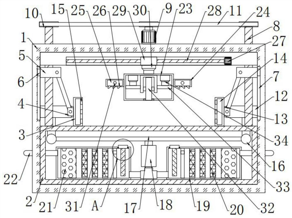
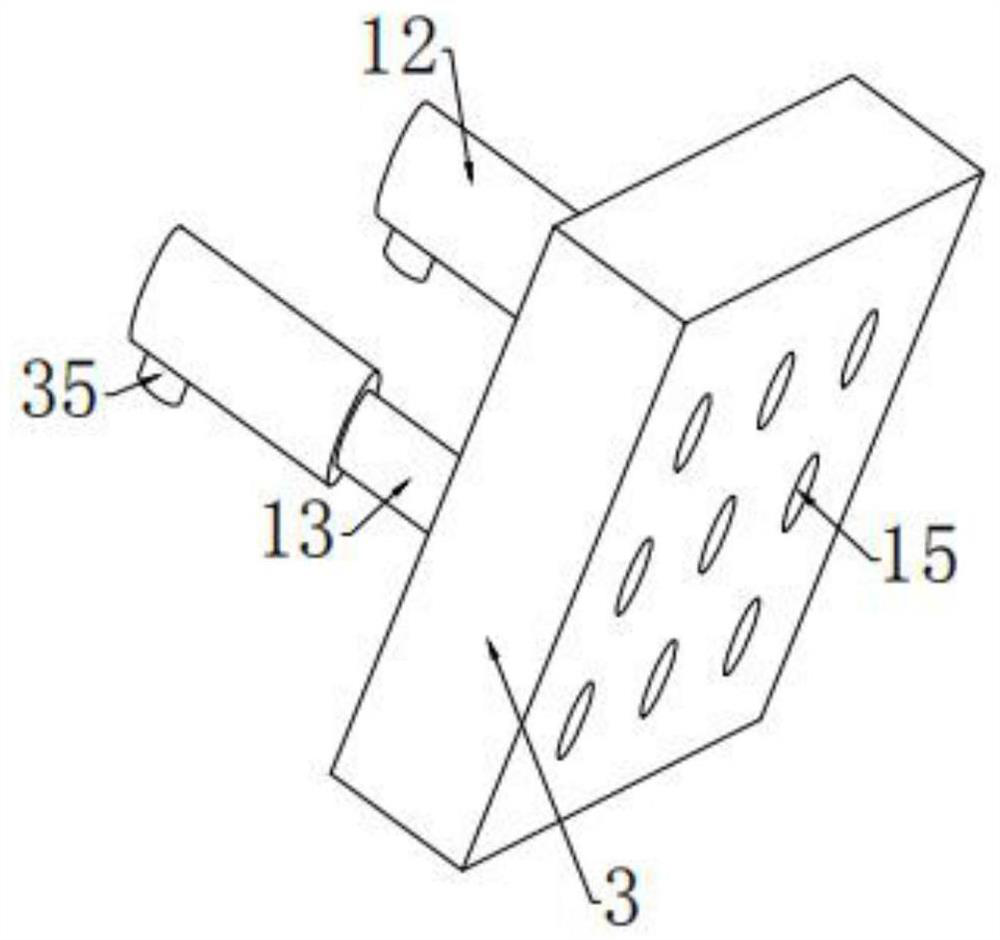
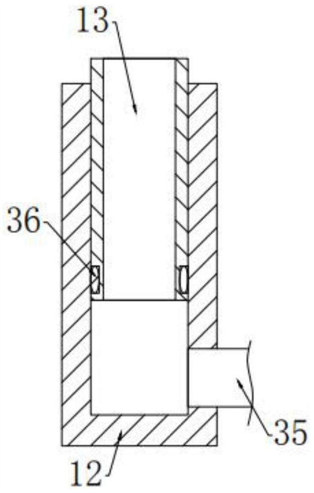
[0026] see Figure 1-4 , in an embodiment of the present invention, a cutting device for parts processing, including a housing 1, the inner side of the housing 1 is fixedly connected with a placement table 2, and the upper side of the placement table 2 is provided with a cutting mechanism, the Clamping mechanisms for fixing parts are arranged on the left and right sides of the cutting mechanism, and the clamping mechanisms are connected with the filter box 19 arranged on the inner side of the placing table 2 through a dust suction mechanism with bolts.

Embodiment 2

[0028] In this embodiment, the clamping mechanism includes a first motor 9 that is bolted to the top of the housing 1, and the left and right sides of the first motor 9 are provided with threaded rods 8 that are rotatably connected to the housing 1. The outside of the threaded rod 8 and the output end of the first motor 9 are fixedly connected with a pulley 10, and the pulleys 10 are connected by a belt 11, and the outside of the threaded rod 8 is threaded to be provided with a movable block 5, and the movable block The outer side of the 5 is fixedly connected with a guide block 6, and the guide block 6 is slidably connected with the guide groove 7 arranged on the inner side of the housing 1, and the lower side of the movable block 5 on the left and right sides is provided with splints that are slidably connected with the placement table 2 3. The outside of the splint 3 is fixedly connected with a connecting block 4, and a connecting rod is hinged between the connecting block 4...


PUM


Abstract

The invention relates to the technical field of metal part cutting, in particular to a cutting device for part machining. The device comprises a shell, a placing table is fixedly connected to the inner side of the shell, a cutting mechanism is arranged at the upper side of the placing table, and clamping mechanisms for fixing parts are arranged at the left side and the right side of the cutting mechanism. The clamping mechanisms are connected with a filter box arranged at the inner side of the placing table in a bolt connection manner through a dust collection mechanism. According to the cutting device, through the arrangement of the dust collection mechanism, chippings generated in the cutting process can be collected through dust collection openings formed in clamping plates, the dust-free cutting effect is achieved, the chippings can be collected through the arrangement of the filter box, the chippings can be conveniently cleaned by people, by arranging an adsorption plate, most of the chippings can be adsorbed, so that the replacement frequency of a filter frame and an activated carbon filter layer is reduced, resources are saved, by arranging an air outlet pipe, the chippings generated in the cutting process can be blown to the left side and the right side, and the dust collection mechanism can conveniently suck the chippings.

Description

technical field [0001] The invention relates to the technical field of metal part cutting, in particular to a cutting device for part processing. Background technique [0002] Metal cutting is a method of material removal and forming in the metal forming process. It still occupies a large proportion in today's mechanical manufacturing. The metal cutting process is a process of interaction between the workpiece and the tool. The tool removes excess metal from the workpiece to be processed. And under the premise of controlling productivity and cost, the workpiece can obtain the geometric accuracy, dimensional accuracy and surface quality that meet the design and process requirements. [0003] The existing cutting device will generate a large amount of debris during the processing, and the debris will be thrown out and splashed due to the high-speed rotation of the cutting gear, which will affect the surrounding environment, and the existing cutting device cannot collect the de...

Claims


Application Information

Patent Timeline
Patent Type & Authority Applications(China)
IPC IPC(8): B23Q3/06B23Q11/00B01D46/12
CPCB23Q3/06B23Q11/0046B01D46/12
Inventor 孟明明
Owner 江苏恒钜精密机械科技有限公司
Why Eureka
Try Eureka