
Melt impacting, crushing and granulating system and method

A granulation and melt technology, which is applied in grain processing and other directions, can solve the problems of high energy consumption, dust pollution of the working environment, and reduced control of granulation effect, and achieves simple operation process, good granulation effect, and energy consumption. low effect

Active Publication Date: 2022-01-04
NORTHEASTERN UNIV
View PDF16 Cites 0 Cited by
  • Summary
  • Abstract
  • Description
  • Claims
  • Application Information

AI Technical Summary

Problems solved by technology

The extrusion crushing method is to pour the solid raw material fragments into the cracks of the crushed parts such as rollers and tooth chains, and use the continuous extrusion force generated by the crushed parts to destroy the solid structure, so that the raw materials are gradually crushed into particles. In addition to the normal metallurgical production process, this method is also suitable for the treatment of waste metallurgical slag accumulated over the years, but the energy consumption of the continuous operation of the supply machine is high, and the degree of control over the granulation effect of the particles decreases with the loss of the broken parts. It is easy to generate dust and pollute the working environment

Method used


Image

  • Melt impacting, crushing and granulating system and method
  • Melt impacting, crushing and granulating system and method
  • Melt impacting, crushing and granulating system and method

Examples


Embodiment 1

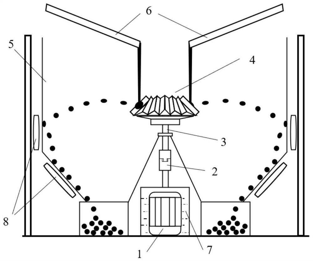
[0050] In this embodiment, the impact member is a bevel gear, and the tooth surface of the bevel gear faces the direction of the melt falling; the number of teeth of the bevel gear is 30, the tooth width is 100 mm, and the indexing cone angle is 45°, and the impact area of ​​the bevel gear is 45°. The average tooth height of the bevel gear is 50mm, and the speed of the bevel gear is 500 r / min (greater than the lower limit of the speed) );

[0051] In this embodiment, the power transmission assembly includes a drive motor 1 and a coupling 2, the drive motor 1 provides a driving force, and the rotating shaft 3 of the impact crushing and granulation assembly is driven to rotate under the connection transmission of the coupling 2, and then Drive the bevel gear 4 as the striker on the shaft.

[0052] The working principle of the system described in this embodiment is:

[0053] Turn on the drive motor 1, and through the connection of the coupling 2, the stably rotating motor shaf...

Embodiment 2

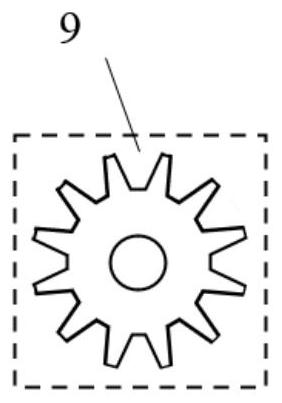
[0055] The impact member described in this embodiment is a cylindrical gear, which is arranged in such a way that the end face of the cylindrical gear faces upwards (the end face of the cylindrical gear faces the falling direction of the melt), and the melt falls between the teeth gaps, and then the tooth surface hits the melt from the side; The number of teeth of the cylindrical gear is 30, the tooth height is 100mm, the tooth pitch is 100mm, and the tooth width is 100mm. ).

[0056] The power transmission assembly described in this embodiment is a gear transmission assembly, which is used to adjust the position and direction of the drive motor and the upper and lower limits of the transmission speed. The gear transmission assembly includes a drive motor that provides rotational power, and is installed on the motor shaft The transmission gear, the transmission gear is connected to the rotating shaft; the transmission gear is a bevel gear, such as Figure 4 As shown, the use...

Embodiment 3

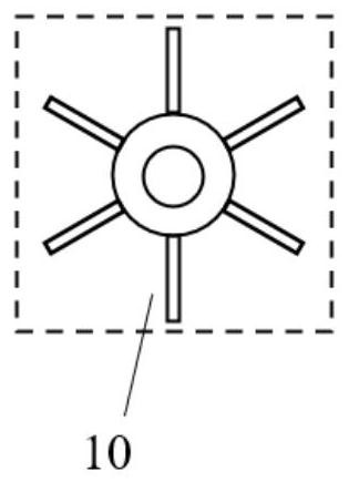
[0059] In this embodiment, the impactor is a drum with fins, and the installation method is that the end face of the drum faces upwards (the end face of the drum faces the direction where the melt falls). Impact the melt, there are 6 fins on the drum, the thickness of the fins along the circumference of the drum is 30mm, the length of the fins along the radial direction of the drum is 100mm, and the length of the fins along the axial direction of the drum is 100mm , the rotational speed of the rotor with fins during work is 1000 rpm (greater than the lower limit of rotational speed ).

[0060] The power transmission assembly described in this embodiment is a gear transmission assembly, which is used to adjust the position and direction of the drive motor and the upper and lower limits of the transmission speed. The gear transmission assembly includes a drive motor that provides rotational power, and is installed on the motor shaft The transmission gear, the transmission ge...


PUM

PropertyMeasurementUnit
Tooth widthaaaaaaaaaa
Tooth heightaaaaaaaaaa
Tooth pitchaaaaaaaaaa

Abstract

The invention provides a melt impacting, crushing and granulating system and method. The melt impacting, crushing and granulating system comprises a power transmission assembly, an impacting, crushing and granulating assembly and a particle collecting assembly; the particle collecting assembly comprises a cylindrical particle collecting device, and an area defined by the inner wall of the particle collecting device is a working cavity of the system; the impacting, crushing and granulating assembly is arranged in the working cavity and comprises a rotating shaft and an impacting piece mounted on the rotating shaft; a bulging structure used for melt impacting is arranged on the impacting piece; the power transmission assembly is arranged outside the working cavity and used for being connected with the rotating shaft and driving the impacting piece to rotate. The invention provides the melt impacting, crushing and granulating system, and relates to a novel dry granulating production technology, namely a melt impacting, crushing and granulating technology, in particular to a granulating technology for impacting the melt through the impacting piece moving at a high speed by utilizing the fluid property of the melt so as to deform and spread the melt and further crush and splash the melt.

Description

technical field [0001] The invention belongs to the technical field of granulation production and waste heat recovery, and in particular relates to a melt impact crushing granulation system and method. Background technique [0002] The granulation production process has a very common demand in production and life. For example, granules are more durable and convenient to use than decoctions, and are more quickly absorbed than tablets; fertilizers are easy to store, transport and use after granulation, which helps It can improve the efficiency of fertilization; molten iron can be made into granules instead of ingots, which can reduce the feeding and production costs for subsequent use; metallurgical slag can be used to produce slag pellets for the production of cement and road pads. Taking the metallurgical industry as an example, according to data from the National Bureau of Statistics of China, China’s pig iron production has reached 808 million tons in 2019, and its by-prod...

Claims


Application Information

Patent Timeline
IPC IPC(8): B02C19/00
CPCB02C19/005B02C19/0056Y02W30/50
Inventor 于庆波康天宇王安邦段文军
Owner NORTHEASTERN UNIV
Learn More