
placement head

A mounting head and mounting technology, which is applied in the direction of assembling printed circuits, printed circuits, and electrical components with electrical components, can solve the problems of bulky, complex software and hardware control systems, and cumbersomeness of the whole machine, and achieve a simple and compact structure. , to avoid the impact force, the effect of uniform weight

Active Publication Date: 2022-03-11
CHANGZHOU MINGSEAL ROBOT TECH CO LTD
View PDF0 Cites 2 Cited by
  • Summary
  • Abstract
  • Description
  • Claims
  • Application Information

AI Technical Summary

Problems solved by technology

The weight and volume of the existing placement head assembly are relatively large, which will cause a large impact force when the placement spindle moves downward at high speed. In order to ensure the placement accuracy and the service life of the machine, it is necessary to increase the corresponding Suspending the placement head assembly and the rail frame that drives its translation eventually leads to a bulky and heavy machine
However, the price of the complete machine using advanced control algorithms and corresponding precise optical, electrical, and mechanical execution equipment is high, and the complex and sophisticated software and hardware control systems are not conducive to further application development.

Method used


Image

  • placement head
  • placement head
  • placement head

Examples


Embodiment Construction

[0029] Embodiments of the present invention are described in detail below, examples of which are shown in the drawings, wherein the same or similar reference numerals designate the same or similar elements or elements having the same or similar functions throughout. The embodiments described below by referring to the figures are exemplary only for explaining the present invention and should not be construed as limiting the present invention.

[0030] In describing the present invention, it should be understood that the terms "center", "longitudinal", "transverse", "length", "width", "thickness", "upper", "lower", "front", " Back", "Left", "Right", "Vertical", "Horizontal", "Top", "Bottom", "Inner", "Outer", "Clockwise", "Counterclockwise", "Axial" , "radial", "circumferential" and other indicated orientations or positional relationships are based on the orientations or positional relationships shown in the drawings, which are only for the convenience of describing the present ...


PUM


Abstract

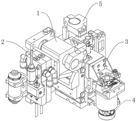
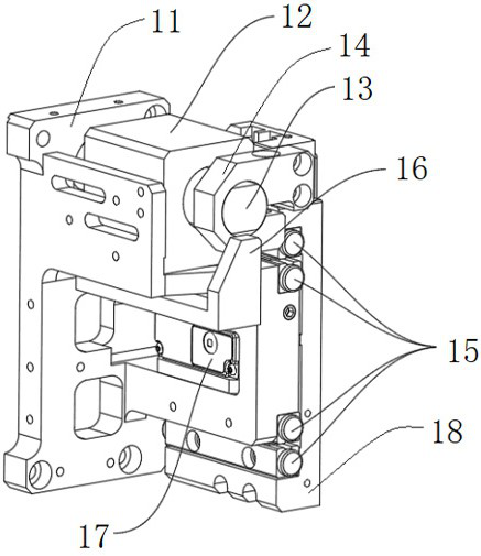
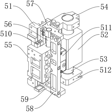
The invention discloses a mounting head, comprising: a y-axis assembly, the y-axis assembly has a first movable end reciprocating along the y-axis; a z-axis assembly, the z-axis assembly is arranged on the first movable end, and the z-axis assembly There is a second movable end that reciprocates along the z-axis; a u-axis assembly, the u-axis assembly is arranged on the second movable end, the u-axis assembly is provided with a suction head, and the u-axis assembly drives the suction head to rotate; the negative pressure unit , the negative pressure unit is arranged on the side of the y-axis assembly away from the z-axis assembly, and the negative pressure unit provides negative pressure for the u-axis assembly. The structure of the present invention is simple and compact, and the negative pressure unit and the z-axis assembly are respectively arranged on both sides of the y-axis assembly, so that the counterweight is more uniform. At the same time, the u-axis assembly is arranged on the z-axis assembly, and the z-axis assembly is arranged on the y-axis assembly. , The optimized structure makes the placement head lighter and avoids large impact.

Description

technical field [0001] The invention belongs to the technical field of mounting, and in particular relates to a mounting head. Background technique [0002] In the intelligent placement equipment, it is necessary to use the placement head to grab the attached components from the placement position to the substrate position, and complete the placement of the components by moving the placement head in the z-axis direction. During the placement process, The control accuracy of placement force will directly affect the placement quality. The weight and volume of the existing placement head assembly are relatively large, which will cause a large impact force when the placement spindle moves downward at high speed. In order to ensure the placement accuracy and the service life of the machine, it is necessary to increase the corresponding Suspending the mounting head assembly and the guide rail frame driving its translation eventually leads to bulky and heavy machine. However, the...

Claims


Application Information

Patent Timeline
Patent Type & Authority Patents(China)
IPC IPC(8): H05K3/30
CPCH05K3/303
Inventor 郜福亮曲东升史晔鑫李长峰唐晓斌章谦胡君君杨健
Owner CHANGZHOU MINGSEAL ROBOT TECH CO LTD
Learn More