Drainer downpipe mounting structure

A technology for installing structures and downpipes, applied to expansion compensation devices for pipelines, pipe components, pipes/pipe joints/fittings, etc., can solve problems such as weld tearing, desoldering or extrusion deformation, gas leakage, etc. Achieve the effect of avoiding pipe blockage, avoiding weld tearing and ensuring service life

Pending Publication Date: 2021-12-31
NANJING IRON & STEEL CO LTD
View PDF0 Cites 0 Cited by
  • Summary
  • Abstract
  • Description
  • Claims
  • Application Information

AI Technical Summary

Problems solved by technology

Existing drainage pipes are usually installed by welding. In the case of large temperature changes, thermal expansion and contraction will cause tearing, desoldering or extrusion deformation of the weld between the drainage pipe and the gas pipe, which is easy to Major accidents such as gas leaks

Method used


Image

  • Drainer downpipe mounting structure

Examples


Embodiment Construction

[0020] In order to make the content of the present invention more clearly understood, the present invention will be further described in detail below based on the specific embodiments and in conjunction with the accompanying drawings.

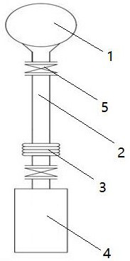
[0021] This embodiment provides a drainer downpipe installation structure, including a gas pipeline 1 arranged along the horizontal direction, a downpipe 2 is fixed and welded vertically at the lower end of the gas pipeline 1 , and the lower end of the downpipe 2 is welded to the drainer 4 . The water in the gas pipeline 1 can flow into the drainer 4 through the downspout 2 and be discharged by the drainer 4 .

[0022] A corrugated expander 3 is fixedly installed on the downspout 2 , and the axis of the corrugated expander 3 coincides with the axis of the downspout 2 . The expansion and contraction of the downpipe 2 can compensate for the length change caused by thermal expansion and contraction through the expansion and contraction of the corr...


PUM


Abstract

The invention discloses a drainer downpipe mounting structure, and relates to the technical field of gas pipelines. The drainer downpipe mounting structure comprises a gas pipeline, a downpipe is connected to the lower end of the gas pipeline, and a corrugated expander is arranged on the downpipe; and a drainer is connected to the lower end of the downpipe. The corrugated expander is mounted on the downpipe, and the length change caused by thermal expansion and cold contraction of the downpipe can be made up through the telescopic property of the corrugated expander, so that the phenomena of weld seam tearing, desoldering or extrusion deformation and the like caused by thermal expansion and cold contraction are effectively avoided, and the service life of the gas pipeline and the downpipe is guaranteed.

Description

technical field [0001] The invention relates to the technical field of gas pipelines, in particular to a drain pipe installation structure. Background technique [0002] In the gas pipelines of iron and steel enterprises, temperature changes will produce water vapor, which will affect the normal use of gas if it is not discharged in time, so a drain pipe will be connected to the gas pipeline. Existing drainage pipes are usually installed by welding. In the case of large temperature changes, thermal expansion and contraction will cause tearing, desoldering or extrusion deformation of the weld between the drainage pipe and the gas pipe, which is easy to Lead to major accidents such as gas leakage. Contents of the invention [0003] The technical problem to be solved by the present invention is to overcome the disadvantages of the prior art and provide a drain pipe installation structure. [0004] In order to solve the above technical problems, the technical solution of the...

Claims


Application Information

Patent Timeline
IPC IPC(8): F16L55/07F16L51/02
CPCF16L55/07F16L51/025
Inventor 李浩蒋卫刚
Owner NANJING IRON & STEEL CO LTD
Why Eureka
Try Eureka