
Plastic product compression device for recycling medical supplies in breast surgery department

A technology of medical supplies and breast surgery, which is applied in the field of compression devices, can solve problems such as low work efficiency, environmental pollution, and fire hazards, and achieve high work efficiency and avoid movement

Pending Publication Date: 2021-12-31
黄国彬
View PDF29 Cites 2 Cited by
  • Summary
  • Abstract
  • Description
  • Claims
  • Application Information

AI Technical Summary

Problems solved by technology

[0004] In order to overcome the disadvantages that plastic medical supplies will produce a large amount of toxic gas during the incineration process, pollute the surrounding environment, work efficiency is still low, and the incineration process takes too long to easily cause fires. The technical problem to be solved is: provide a convenient People recycle plastic medical supplies without affecting the surrounding environment, high work efficiency, and a plastic compression device for breast surgery medical supplies that is not easy to cause fire

Method used


Image

  • Plastic product compression device for recycling medical supplies in breast surgery department
  • Plastic product compression device for recycling medical supplies in breast surgery department
  • Plastic product compression device for recycling medical supplies in breast surgery department

Examples


Embodiment 1

[0036] A plastic article compression device for the recycling of breast surgical medical articles, such as Figure 1-Figure 3 As shown, it includes a sealed cabinet 1, a buffer base 2, an isolation baffle 3, a lift push rod 5, a compression button 51, a release button 52, a sealing mechanism 6 and a compression mechanism 7. The outer bottom of the sealed cabinet 1 is provided with buffers at intervals. The base 2, the upper part of the sealed cabinet 1 is provided with an isolation baffle 3, the upper part of the sealed cabinet 1 is provided with a lift push rod 5, the left side of the sealed cabinet 1 is provided with a compression button 51 on the front side, and the left side of the sealed cabinet 1 A release button 52 is arranged on the front side of the upper part, a sealing mechanism 6 is arranged on the sealed cabinet 1 , and a compression mechanism 7 is arranged between the sealed cabinet 1 and the lift push rod 5 .

[0037]The sealing mechanism 6 includes a sealing ca...

Embodiment 2

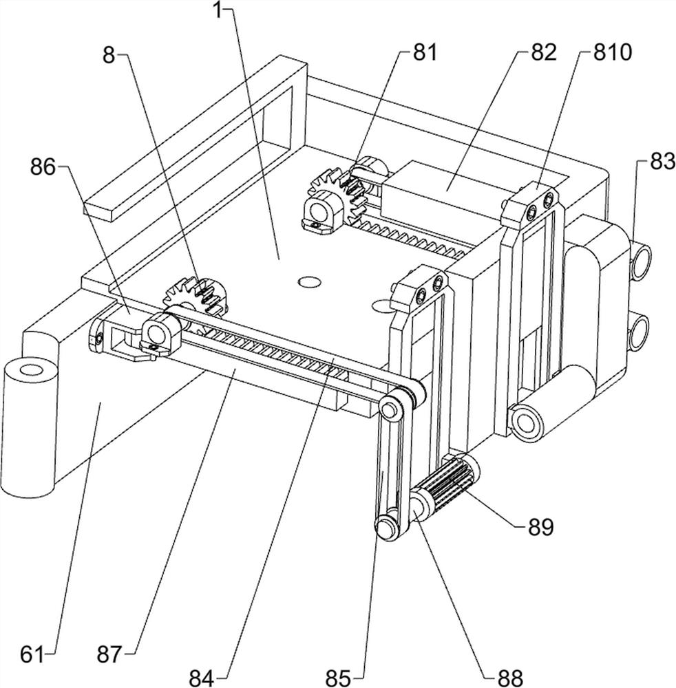
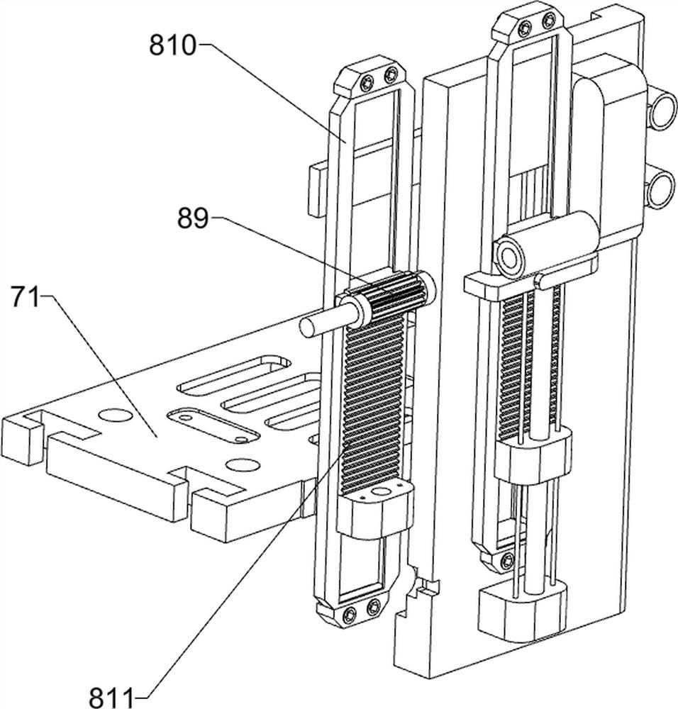
[0041] On the basis of Example 1, as Figure 5-Figure 10 As shown, it also includes a sealing auxiliary mechanism 8, and the sealing auxiliary mechanism 8 includes a positioning gear 81, a safety cover 82, a fixed column 83, a first transmission assembly 84, a second transmission assembly 85, a mounting seat 86, a telescopic rack 87, The positioning shaft 88, the driving gear 89, the fixed guide cover 810, the driving tooth plate 811 and the top block 812, the positioning gear 81 is symmetrically rotated on the front side of the inner bottom of the isolation baffle 3, and the upper part of the outer rear side of the sealed cabinet 1 is spaced There is a fixed column 83, two fixed columns 83 are a group, a safety cover 82 is arranged between the two fixed columns 83 and the inner bottom of the isolation baffle 3, and the left and right parts of the isolation baffle 3 are slidingly provided with telescopic racks 87, the telescopic rack 87 meshes with the positioning gear 81, the...

Embodiment 3

[0046] On the basis of Example 1 and Example 2, as Figure 11-Figure 14 As shown, a locking mechanism 10 is also included. The locking mechanism 10 includes an electromagnetic lock 101, a lifting slider 102, a contact switch 103 and a support spring 104. The lower part of the auxiliary guide rail 76 is slidably provided with a lifting slider 102. A contact switch 103 is provided, a support spring 104 is wound between the bottom of the lifting slider 102 and the lower part of the auxiliary guide rail 76 , and an electromagnetic lock 101 is provided in the middle of the left part of the sealed cabinet door 61 .

[0047] It also includes an anti-overflow mechanism 11. The anti-overflow mechanism 11 includes a telescopic plate 112, a synchronous positioning block 113 and a compression spring 114. The left and right sides of the inner rear of the sealed cabinet 1 are symmetrically provided with telescopic plates 112 up and down, and the upper and lower sides are telescopic. A synch...


PUM


Abstract

The invention relates to a compression device, in particular to a plastic product compression device for recycling medical supplies in the breast surgery department. The invention needs to design the plastic product compression device for recycling the medical supplies in the breast surgery department, so that people can recycle the plastic medical supplies conveniently, the surrounding environment is not affected, the working efficiency is high, and fire disasters are not prone to being caused. The plastic product compression device for recycling the medical supplies in the breast surgery department comprises a sealed cabinet body, an isolation baffle plate and a lifting push rod, wherein buffer bases are arranged on the sealed cabinet body at intervals; the isolation baffle plate is arranged on the sealed cabinet body; and the lifting push rod is mounted on the sealed cabinet body. According to the plastic product compression device for recycling the medical supplies in the breast surgery department provided by the invention, a sealing mechanism is opened, then a proper amount of plastic supplies are placed in the plastic supply sealed cabinet body, an air cylinder is started to stretch out and draw back, and then the plastic medical supplies are compressed through the compression mechanism, so that people can recycle the plastic medical supplies conveniently, the surrounding environment is not affected, and the working efficiency is high.

Description

technical field [0001] The invention relates to a compression device, in particular to a compression device for plastic articles used for the recovery of medical articles for breast surgery. Background technique [0002] When plastic medical supplies are used up, they must be recycled. At present, most of the plastic medical supplies are recycled manually. First, people put the plastic medical supplies into the collection container, and then they will be incinerated for recycling. The plastic medical supplies will generate a large amount of toxic gas during the incineration process, which is harmful to the surrounding environment. Cause pollution, work efficiency is still low, and plastic medical supplies take too long in the incineration process, which is easy to cause fire. [0003] Therefore, it is necessary to design a plastic article compression device for breast surgery medical article recycling, which is convenient for people to recycle plastic medical articles, does...

Claims


Application Information

Patent Timeline
IPC IPC(8): B29B17/00
CPCB29B17/0047Y02W30/62
Inventor 黄国彬
Owner 黄国彬
Learn More