Turning lens cone assembly based on rolling and pitching platform and assembling and adjusting method thereof

A technology of turning mirrors and components, applied in the directions of installation, optical components, optics, etc., can solve the problems of increased load of the rolling platform, no installation and adjustment plan expression, etc., to meet the requirements of position accuracy, meet the requirements of imaging quality, and simple structure. Effect

Pending Publication Date: 2021-12-28
SHANGHAI AEROSPACE CONTROL TECH INST
View PDF0 Cites 0 Cited by
  • Summary
  • Abstract
  • Description
  • Claims
  • Application Information

AI Technical Summary

Problems solved by technology

[0004] After searching, it was found that Chinese Patent Publication No. CN1092543392A discloses a miniaturized rolling-upward long-wave cooling optical system. This patent discloses a three-time right-angle reentry optical system. plan to express
And its detector components are placed on the rolling platform to follow up together, increasing the load on the rolling platform

Method used


Image

  • Turning lens cone assembly based on rolling and pitching platform and assembling and adjusting method thereof
  • Turning lens cone assembly based on rolling and pitching platform and assembling and adjusting method thereof
  • Turning lens cone assembly based on rolling and pitching platform and assembling and adjusting method thereof

Examples


Embodiment Construction

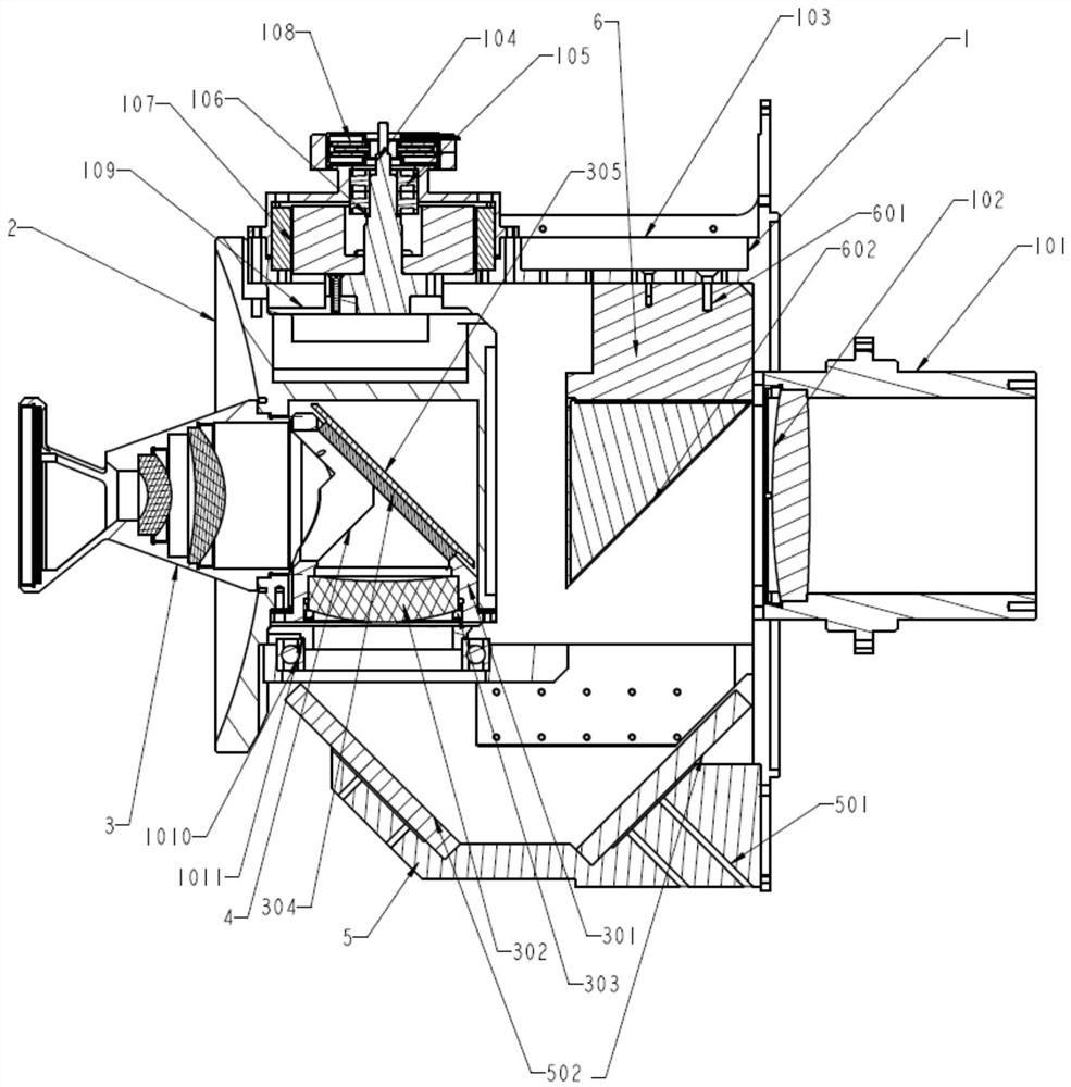
[0037] Such as Figure 1-4 As shown, the present invention relates to a turning lens barrel assembly based on a rolling platform, including: a rolling frame platform part 1, an inner frame 2, a secondary lens barrel assembly 3, a mirror seat assembly 4, and a mirror seat assembly 2 3. Mirror seat three components 6.

[0038] The rolling frame platform component 1 includes a rolling shaft 101, a rolling shaft inner lens 102, a rolling frame 103, a pitching shaft 104, a pitching frame bearing one 105, a bearing gasket one 106, a pitching frame motor 107, and a pitching frame code disc 108, casing 109, pitch frame bearing 2 1010, bearing gasket 2 1011;

[0039] The rolling frame 102 is a structure with a central hole and two vertical ears, and each of the vertical ears has a hole coaxial with each other;

[0040] The roll shaft 101 and the center hole of the roll frame 102 are matched with high precision through the shaft hole, and are fastened and connected with screws. The ce...


PUM


Abstract

The invention discloses a turning lens cone assembly based on a rolling and pitching platform and an assembling and adjusting method thereof. The assembling and adjusting methodcomprises the following steps of firstly, respectively assembling and adjusting a rolling and pitching frame platform part, a secondary lens cone assembly, a first reflector base assembly, a second reflector base assembly and a third reflector base assembly, assembling and adjusting all the assemblies, and then conducting overall joint debugging and convergence. The mechanical assembling and adjusting of the rolling and pitching frame platform part are carried out under the conditions that a rolling frame rotating shaft and a pitching frame rotating shaft can freely and easily rotate, clamping stagnation is avoided, and a frame is gapless, and the assembling and adjusting of the rolling and pitching frame platform part can be realized by assembling and adjusting the coaxiality and the gap of a frame bearing under the condition that the part machining precision meets the design precision; a rolling and pitching frame platform component is assembled and adjusted, and the purpose is to coincide an incident visual axis of a rolling optical system and a rotating shaft of a rolling frame; the center of the optical axis of the first right-angle reflex needs to coincide with the rotating shaft of the pitching frame; through second, third and fourth times of right-angle refraction and reflection, the center of the light is always on the intersecting plane of the pitch axis and the rotating shaft of the rolling frame; and the center of the optical axis is returned to the coincident direction of the rolling and pitching axis through four times of right-angle reflex.

Description

technical field [0001] The invention belongs to the field of precision mechanical design machinery, and specifically relates to a multi-dimensionally adjusted lens barrel assembly. Through mechanical structure adjustment, the multi-dimensional turning optical system achieves high imaging quality and positioning accuracy. Background technique [0002] In a complete optical-mechanical system, the design of the optical system and the design of the mechanical structure complement each other. A good optical system and the realization of the functions of optical components require the support and accuracy of the mechanical structure. Therefore, in the optical system, the mechanical structure Design played a crucial role. For the design of optomechanical systems, there are many factors that affect its final accuracy and performance, such as structural rationality, part accuracy, stiffness and strength, and assembly accuracy between parts. However, blindly using high-precision part...

Claims


Application Information

Patent Timeline
IPC IPC(8): G02B7/182G02B7/198G02B7/02
CPCG02B7/182G02B7/1821G02B7/021G02B7/026
Inventor 陈宗镁杨俊彦刘浩伟龙华保邵艳明陈寰高冬阳陈龙江
Owner SHANGHAI AEROSPACE CONTROL TECH INST
Why Eureka
Try Eureka