Power conversion device

A technology of a power conversion device and a switching element, which is applied in the output power conversion device, the conversion of AC power input into DC power output, and the conversion of irreversible DC power input into AC power output, etc., can solve problems such as easy generation of overcurrent.

Pending Publication Date: 2021-12-24
PANASONIC INTELLECTUAL PROPERTY MANAGEMENT CO LTD
View PDF7 Cites 0 Cited by
  • Summary
  • Abstract
  • Description
  • Claims
  • Application Information

AI Technical Summary

Problems solved by technology

[0006] If a momentary voltage drop occurs, it is easy to generate overcurrent

Method used


Image

  • Power conversion device
  • Power conversion device
  • Power conversion device

Examples


Embodiment Construction

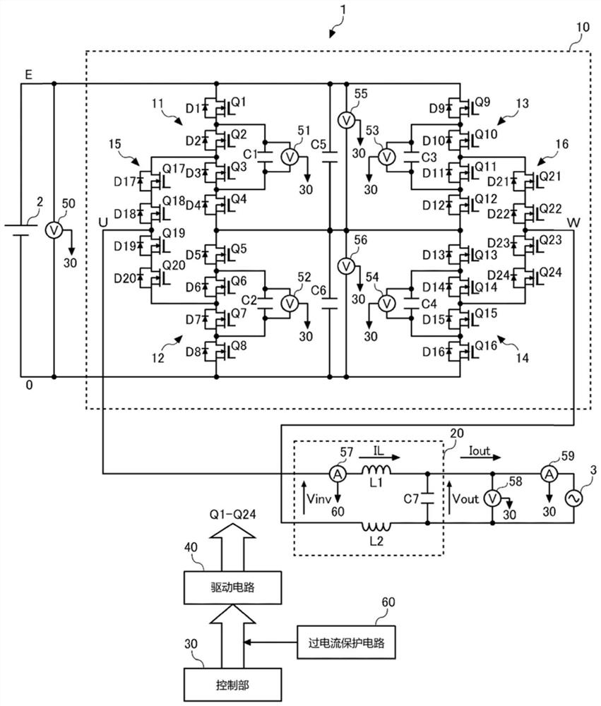
[0030] figure 1 It is a figure for demonstrating the structure of the power conversion apparatus 1 of embodiment. The power conversion device 1 converts DC power supplied from a DC power supply 2 into AC power, and outputs the converted AC power to a commercial power system (hereinafter, simply referred to as a system 3 ). The DC power supply 2 is composed of, for example, a distributed power supply (solar battery, storage battery, fuel cell, etc.) and a DC / DC converter capable of controlling the output of the distributed power supply. The DC / DC converter and the power conversion device 1 are connected by a DC bus. In addition, the DC power supply 2 may be configured by connecting a distributed power supply and a DC / DC converter in parallel.

[0031] The power conversion device 1 includes an inverter circuit 10 , a filter circuit 20 , a control unit 30 , a drive circuit 40 , and an overcurrent protection circuit 60 . The inverter circuit 10 converts the DC voltage supplied ...


PUM


Abstract

According to the present invention, an inverter circuit 10 includes a plurality of flying capacitors C1-C4 and converts DC voltage supplied from a DC power supply 2 to AC voltage. A filter circuit 20 makes the waveform of the output voltage of the inverter circuit 10 approximate a sine wave. An overcurrent protection circuit 60 supplies a block signal for turning off a plurality of switching elements Q1-Q24 to a drive circuit 40 when an overcurrent is detected. When at least one of a voltage abnormality of any of the plurality of flying capacitors C1-C4 and an abrupt variation of the output voltage of this power conversion device 1 occurs, a voltage other than the positive voltage of the DC power supply 2, the negative voltage of the DC power supply 2, and zero voltage is restricted to be output from the inverter circuit 10.

Description

technical field [0001] The present disclosure relates to power conversion devices that convert DC power to AC power. Background technique [0002] Efficient power conversion and compact design are desired for power conditioners connected to solar cells, storage batteries, fuel cells, and the like. Since the multilevel power conversion device can reduce the voltage applied to the switching element, it is possible to reduce switching loss and realize efficient power conversion. As a typical implementation method of a multilevel power converter, there is a flying capacitor method (for example, refer to Patent Document 1). [0003] MOSFETs (Metal-Oxide-Semiconductor Field-Effect Transistors: Metal-Oxide-Semiconductor Field-Effect Transistors) with a withstand voltage of 600 V, 300 V, and 150 V are often used as switching elements for inverters used in power conditioners. Generally, when the withstand voltage of the switching element is low, the conduction loss and the switchin...

Claims


Application Information

Patent Timeline
Patent Type & Authority Applications(China)
IPC IPC(8): H02M7/48H02M7/483
CPCH02M7/4837H02M1/325H02M1/0009H02M7/487H02M1/0095H02M1/32H02M7/483H02M1/0003H02M7/5395
Inventor 花村贤治堀尾涉藤井裕之广田翔吾
Owner PANASONIC INTELLECTUAL PROPERTY MANAGEMENT CO LTD
Why Eureka
Try Eureka