Device and method for realizing large-scale optical CLOS network interconnection, equipment and medium

A network interconnection and optical interconnection technology, which is applied in the field of devices for realizing large-scale optical CLOS network interconnection, can solve the problems of complex optical fiber connection, optical interconnection network complexity, complex optical fiber wiring, etc. Simplified complexity, optimized fiber optic cabling

Pending Publication Date: 2021-12-24
ZTE CORP
View PDF0 Cites 0 Cited by
  • Summary
  • Abstract
  • Description
  • Claims
  • Application Information

AI Technical Summary

Problems solved by technology

[0003] However, in a large-scale communication equipment system in which all interconnection units are optically interconnected, the general connection units are interconnected using a CLOS topology network, which makes the optical fiber connections between optical interconnection units very complicated. The optical fiber of the unit will be connected to multiple optical interconnection units
In addition, in the same optical interconnection unit, the optical fibers may belong to different optical engines, and these optical interconnection units have a certain distance in space, and the optical interconnection units are directly connected by optical fibers, resulting in the wiring of optical fibers Very complex, and the complexity of the optical interconnection network within and between large-scale equipment leads to a series of problems in equipment production, deployment, expansion, etc.

Method used


Image

  • Device and method for realizing large-scale optical CLOS network interconnection, equipment and medium
  • Device and method for realizing large-scale optical CLOS network interconnection, equipment and medium
  • Device and method for realizing large-scale optical CLOS network interconnection, equipment and medium

Examples


Embodiment 1

[0051] Embodiment 1: Glass-based optical waveguide interconnection board

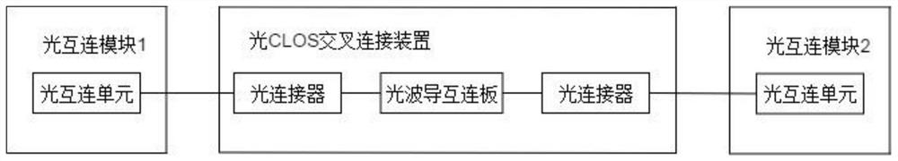
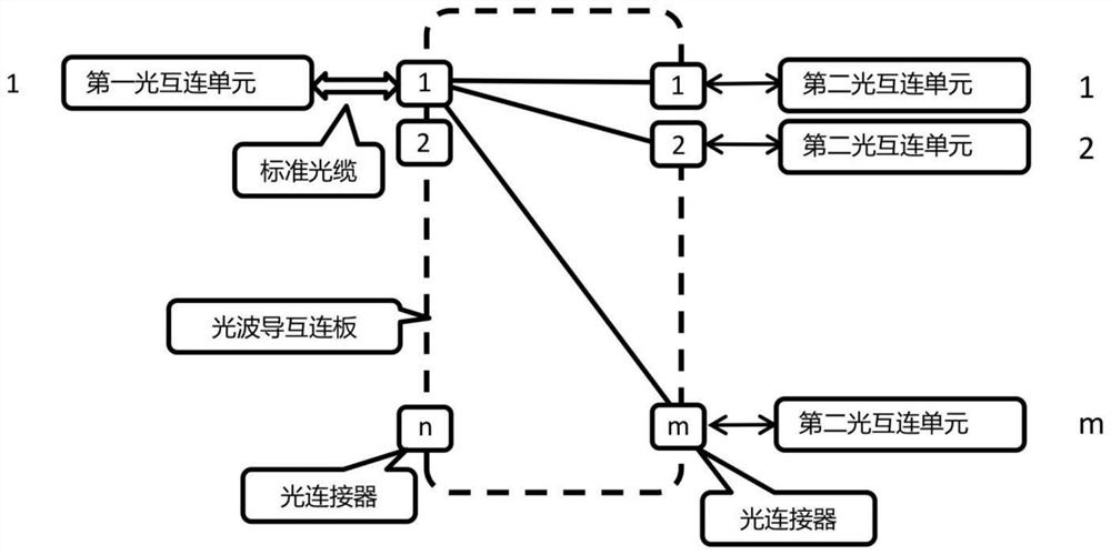
[0052] The optical waveguide interconnection board is the core part of the embodiment of the present invention. The complexity of the CLOS network interconnection is realized by the optical waveguide interconnection board, so the optical fiber interconnection for external interconnection can use standard fiber sequences. The optical CLOS cross-connect device of this embodiment uses high-density optical connectors and glass-based optical waveguide interconnection boards. The reason why waveguides are used as interconnection boards is mainly to consider that the optical paths in the waveguides can pass through each other almost perfectly without generating Mutual interference, that is, in one layer of waveguides, can integrate a very large number of cross interconnection networks.

[0053] The glass base is used because of the loss and cost advantages of the glass base. The glass base waveguide produced b...

Embodiment 2

[0056] Embodiment 2: polymer-based optical waveguide interconnection board, the use of polymer base is mainly because the fusion of polymer waveguide and existing PCB board is better, and it can be conveniently made as an optical waveguide interconnection board with photoelectric hybrid, Other references to Embodiment 1 will not be repeated here.

Embodiment 3

[0057] Embodiment 3: Optical CLOS cross-connect device for white box switch

[0058] Such as Figure 7 As shown, this embodiment adopts a box body in structure, and adopts a uniform size with other white boxes in the rack. The size of the optical waveguide interconnection board can also be adjusted according to the specific size. At the same time, a unified operation display and other electrical functions can be designed according to the unified style of the whole machine to realize the actual deployment of photoelectric hybrid.

[0059] The white box switch includes an upper panel, a lower panel, a front panel, and a rear panel. An optical waveguide interconnection board is respectively installed on the upper and lower layers of the panel, which are used to correspond to two interconnected fullmesh networks of the CLOS network. Then an optical CLOS The network cross interconnection box can support a complete optical interconnection device; that is: the optical waveguide inte...


PUM


Abstract

The embodiment of the invention discloses a device and method for realizing interconnection of a large-scale optical CLOS network, equipment and a medium, relates to the technical field of telecommunication equipment, and solves the technical problem that optical fiber wiring is complicated when the optical CLOS network is used as a connecting unit for interconnection. According to the technical scheme, at least two optical interconnection modules are arranged; each optical interconnection module comprises at least one optical interconnection unit, and the optical CLOS cross connection device comprises an optical waveguide interconnection plate, an optical connector and a structural body, wherein the optical waveguide interconnection plate and the optical connector are fixed through the structural body, and the optical interconnection unit is connected with the optical waveguide interconnection board through the optical connector. According to the device and the method, when equipment networking is carried out, optical fiber wiring is greatly optimized, the individual requirements of optical fiber interconnection are shielded, the complexity of optical fiber connection between optical interconnection units is greatly simplified, the deployment speed of the equipment is increased, and the deployment quality of the equipment is improved.

Description

technical field [0001] The present disclosure relates to the technical field of telecommunication equipment, in particular to the optical interconnection of data switches, routers, SRs, BRASs, and large-scale wavelength division equipment, and in particular to a device, method, equipment, and medium for realizing the interconnection of large-scale optical CLOS networks. Background technique [0002] As the difficulty of high-density electrical interconnection on the backplane of large-scale communication switching equipment becomes more and more difficult, the call for optical interconnection inside and between switching equipment is getting higher and higher. Compared with the electrical interconnection, the optical interconnection inside the device has many natural advantages. One very important advantage is that it breaks through the restriction of the 40-inch length of the electrical backplane and decouples the connection between the line card and the switch card inside t...

Claims


Application Information

Patent Timeline
Patent Type & Authority Applications(China)
IPC IPC(8): H04Q11/00
CPCH04Q11/0005H04Q2011/0056H04Q2011/0007
Inventor 汤宁峰种海宁高宇琦华锋尚迎春陈勋
Owner ZTE CORP
Why Eureka
Try Eureka