
Light source module and lighting apparatus, and illumination apparatus using same

a technology of led modules and lighting devices, which is applied in the direction of fixed installation, lighting and heating devices, instruments, etc., can solve the problems of increased manufacturing costs of led modules, reduced service life, and complicated wiring for connecting led modules to lighting devices, etc., and achieves low cost

Active Publication Date: 2011-09-01
PANASONIC CORP
View PDF5 Cites 57 Cited by
  • Summary
  • Abstract
  • Description
  • Claims
  • Application Information

AI Technical Summary

Benefits of technology

[0013]In view of the above, the present invention provides a light source module, a lighting apparatus and an illumination apparatus using the light source module and the lighting apparatus capable of responding to technological improvement of LEDs and being manufactured at low cost.
[0014]Furthermore, the present invention provides a lighting apparatus capable of turning on / off multiple types of light source modules with different electrical characteristics with a low manufacturing cost and simple wiring.
[0016]With this configuration, since the characteristic information on the electrical characteristics of the LEDs is preset in the characteristic setting unit, it is possible to cope with technological improvement of LEDs.

Problems solved by technology

If 4 LEDs with the same characteristic connected in series are connected to the illuminating device, an overvoltage is applied, resulting in over-current.
However, if 0.3 A flows through an LED module with an output current of 0.2 A, abnormal heat is generated due to the over current, resulting in a breakdown or lifetime reduction.
However, in Reference 3, since an electrically programmable non-volatile semiconductor memory such as a flash memory is needed, manufacturing cost of the LED module increases.
This makes wiring for connection between the LED module and the lighting apparatus complicated.

Method used


Image

  • Light source module and lighting apparatus, and illumination apparatus using same
  • Light source module and lighting apparatus, and illumination apparatus using same
  • Light source module and lighting apparatus, and illumination apparatus using same

Examples


first preferred embodiment

[0067]Examples of a first preferred embodiment in accordance with the present invention will now be described.

Example 1

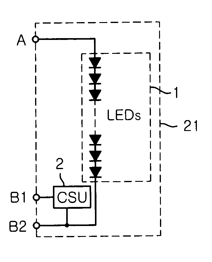
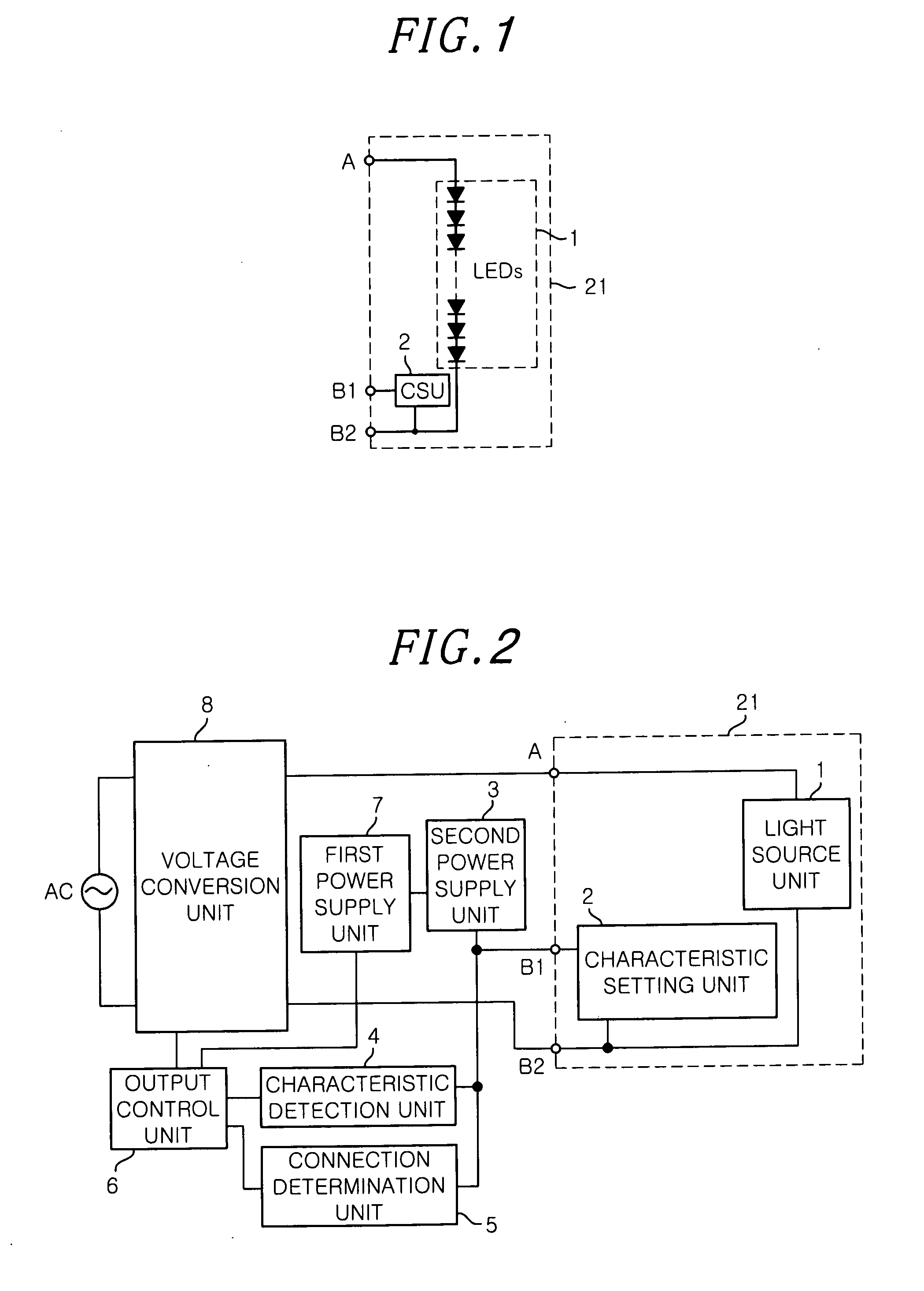
[0068]Referring to FIG. 1, the LED module 21 includes a light source unit 1 in which a plurality of light emitting diodes (LEDs) are connected in series; and a characteristic setting unit (CSU) 2 for setting characteristic information of the LEDs, e.g., information corresponding to a targeted current value. A positive terminal of the light source unit is coupled to a connecting terminal A which can be electrically connected to or disconnected from a lighting apparatus disposed outside the LED module 21. A negative connecting terminal of the light source unit 1 is coupled to a connecting terminal B2. The characteristic setting unit 2 is connected between the low potential terminal (i.e., the negative connecting terminal) of the light source unit 1 and a connecting terminal B1.

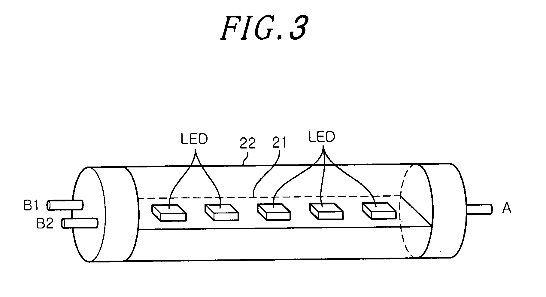
[0069]FIG. 3 shows an exemplified configuration of the LED module 21. As shown in FIG. 3, on...

example 6

[0154]FIGS. 21 and 22 illustrate circuit diagrams of a lighting apparatus of Example 6. In this example, the lighting apparatus capable of turning on both direct-current driven light sources such as the LEDs described in Examples 1 to 5 and alternating-current driven fluorescent lamps will be described. FIG. 21 shows a basic configuration of the lighting apparatus with an LED module 21 connected thereto, and FIG. 22 presents a basic configuration of the lighting apparatus with a fluorescent lamp La connected thereto.

[0155]In FIG. 21, the configuration of the LED module 21 is basically the same as that described in Example 4 as shown in FIG. 14. The difference is that there are provided connecting terminals A1, A2 and A3, connecting terminals B1, B2 and B3, and characteristic setting units 2a and 2b having the same circuit and the same circuit constant, characteristic setting units 2a and 2b being located between the connecting terminals A1 and A2 and between the connecting terminals...

second preferred embodiment

[0176]Next, examples of a second preferred embodiment in accordance with the present invention will be described. Throughout the drawings, like reference numerals will be given to same parts as that in the above described examples.


PUM


Abstract

A light source module includes a substrate unit for mounting multiple light emitting diodes thereon to electrically connecting them; first and second electrical connecting terminals for supplying a current to the light emitting diodes based on a voltage applied from outside the substrate unit; and a characteristic setting unit for presetting characteristic information corresponding to a electrical characteristic of the light emitting diodes. Further, the light source module includes a third electrical connecting terminal for outputting a setting signal based on the characteristic information preset in the characteristic setting unit, and the characteristic setting unit is connected at least between the third and first electrical connecting terminals or between the third and second electrical connecting terminals, and the characteristic setting unit responds to a set-up power inputted from the third electrical connecting terminal to generate the setting signal.

Description

FIELD OF THE INVENTION[0001]The present invention relates to a light source module using light emitting diodes as a light source, a lighting apparatus for turning the light source module on / off and an illumination apparatus using the light source module and the illuminating device.BACKGROUND OF THE INVENTION[0002]Conventionally, fluorescent lamps have been mainly used as a light source for illumination, and illumination apparatuses turned on by using a high-frequency inverter switching device have been widely spread. Recently, light emitting diodes (LEDs) are spotlighted as an electrical light source other than discharge lamps such as fluorescent lamps. In particular, since the LEDs have a relatively longer lifetime than fluorescent lamps, they are expected to become superior to the fluorescent lamp FHF32 mainly used for base lighting by future technological improvement.[0003]As LED technology improves, there is developed a light source module with LEDs mounted thereon. In the light...

Claims


Application Information

Patent Timeline
Patent Type & Authority Applications(United States)
IPC IPC(8): H05B37/02
CPCF21K9/17F21S8/031H05B33/0806F21Y2103/003F21Y2101/02F21K9/27F21Y2103/10F21Y2115/10H05B45/375H05B45/3725H05B45/38H05B45/395
Inventor HAMAMOTO, KATUNOBUHORIGUCHI, AKIRASUGAWARA, HIROSHIMITSUYASU, KEI
Owner PANASONIC CORP
Learn More