
Liquid crystal display module assembly equipment

A liquid crystal display module and assembly equipment technology, applied in nonlinear optics, instruments, optics, etc., can solve the problems of high use and debugging cost, low economic benefit, complex structure, etc., and achieve the effect of rapid assembly and connection

Pending Publication Date: 2021-12-24
江苏聚龙显示科技有限公司
View PDF0 Cites 0 Cited by
  • Summary
  • Abstract
  • Description
  • Claims
  • Application Information

AI Technical Summary

Problems solved by technology

[0003] The liquid crystal display module usually needs to be connected to the corresponding PCB socket during the production process, and it needs to be positioned when connecting the PCB socket. The current positioning method mainly uses an industrial CCD camera for visual positioning, but the structure of this positioning method is relatively complicated and uses The debugging cost is also relatively high, and in some low-demand assembly occasions, the economic benefit of using is relatively low

Method used


Image

  • Liquid crystal display module assembly equipment
  • Liquid crystal display module assembly equipment
  • Liquid crystal display module assembly equipment

Examples


Embodiment

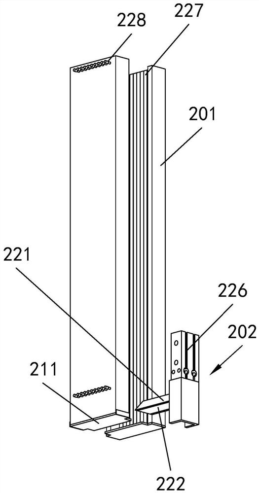
[0022] Example: see Figure 1-6 , a liquid crystal display module assembly equipment, including a support frame 100 and a PCB board crimping assembly 200, the support frame 100 is in the shape of a cube, and the PCB board crimping assembly 200 is installed in the support frame 100, which includes a tube shell 201 and abutment Pressing mechanism 202, the tube shell 201 is provided with a through groove along the vertical direction, the left and right ends of the through groove all pass through the tube shell 201, the upper and lower ends of the tube shell 201 are open, and the lower end of the tube shell 201 is connected to a For the limit plate 211 arranged horizontally, a torsion spring is sleeved on the rotating shaft, and the torsion spring acts on the limit plate 211 and makes it abut against the bottom surface of the tube shell 201. A pair of limit plates 211 are located on the tube shell 201 respectively. The front and rear sides of the front and back, and there is a gap...


PUM


Abstract

The invention discloses liquid crystal display module assembly equipment. The equipment comprises a support frame and a PCB crimping assembly; the support frame is cubic; the PCB crimping assembly is mounted in the support frame and comprises a tube shell and a pressing mechanism; the tube shell is provided with through grooves along the vertical direction; the left and right ends of the through grooves penetrate through the tube shell; the upper end and the lower end of the tube shell are open; and the lower end of the tube shell is rotationally connected with a pair of limiting plates through a rotating shaft. The PCB crimping assembly of the assembly equipment comprises the tube shell and the pressing mechanism, the tube shell is provided with the through grooves in the vertical direction, the pressing mechanism is arranged on the side portion of the tube shell and comprises a separating plate and pressing plates; in the assembling process, PCBs can be contained and positioned through the through grooves in the tube shell, after every two adjacent PCBs are separated through the separating plate, the pressing plates are used for pressing and connecting the independent PCBs, and therefore, rapid assembling and connecting of the PCBs are achieved.

Description

technical field [0001] The invention relates to the field of liquid crystal display module production, in particular to a liquid crystal display module assembly equipment. Background technique [0002] The LCD module mainly includes screen and backlight components. The display part of the LCD TV is the liquid crystal module, which is equivalent to the picture tube in the CRT. Other parts include power supply circuits, signal processing circuits, etc., and of course the casing. The module is mainly divided into screen and backlight components. The two parts are assembled together but work independently of each other. [0003] The liquid crystal display module usually needs to be connected to the corresponding PCB socket during the production process, and it needs to be positioned when connecting the PCB socket. The current positioning method mainly uses an industrial CCD camera for visual positioning, but the structure of this positioning method is relatively complicated a...

Claims


Application Information

Patent Timeline
IPC IPC(8): G02F1/13
CPCG02F1/1303
Inventor 任皖生
Owner 江苏聚龙显示科技有限公司
Learn More