


Quick Research
Generate reliable direction feasibility study reports for your R&D in just a few steps.

Technical Q&A
Discover and master advanced knowledge NOW. Basics, ideas, possibilities, all at once.

Find Solutions
As an expert in R&D theories, this can generate solutions to your technical problems instantly.

Evaluate Feasibility
Analyze your overall solution with one click, know your potential R&D risks in advance.

Monitor Landscape
Get weekly tech updates, stay abreast of the latest tech innovations and key insights.
A telescopic vortex generator and the propeller hub it constitutes
A vortex generator, telescopic technology, applied to the propeller, through the generation of vortex, drag reduction and other directions, can solve the problems of poor operability, poor adaptability, troublesome loading and unloading, etc., and achieve the effect of simple operation, good adaptability, and convenient loading and unloading
- Summary
- Abstract
- Description
- Claims
- Application Information
AI Technical Summary
Problems solved by technology
Method used
Image

Examples
Embodiment 1
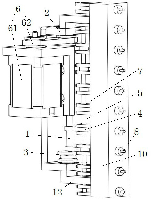
[0042] Such as Figure 1 to Figure 3 As shown, a telescopic vortex generator includes a pivot 1, a rotating connection block 4, a connecting rod 5, a driving device 6, a connecting rod seat 7, and a raised structure 8, and the pivot 1 and the driving device 6 connected, the driving device 6 is used to drive the pivot 1 to make a circular motion on a plane perpendicular to the axis centerline of the pivot 1, the pivot 1 is connected to the rotating connecting block 4, and the rotating connecting block 4 is connected to the rotating connecting block 4 The connecting rod 5 is rotationally connected, the connecting rod 5 is connected to the connecting rod base 7, the connecting rod base 7 is connected to the protruding structure 8, and the protruding structure 8 can pass through the middle of the propeller hub Shaft fairing.
[0043] During work, the driving device 6 drives the pivot 1 to make a circular motion on a plane perpendicular to the center line of the pivot 1 axis, and th...
Embodiment 2
[0055] Such as Figure 1 to Figure 3 As shown, as a further optimization of Embodiment 1, this embodiment includes all the technical features of Embodiment 1. In addition, this embodiment also includes the following technical features:
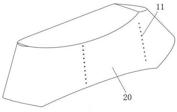
[0056] As a preferred technical solution, it also includes a guide rail 10, the guide rail 10 is provided with a through hole 11 matched with the protruding structure 8, and the protruding structure 8 passes through the guide rail 10 along the through hole 11.
[0057] The guide rail 10 acts as a limiter for the protruding structure 8, which is beneficial to prevent the protruding structure 8 from rotating, thereby restricting the protruding structure 8 from rotating and realizing linear motion, thereby improving the stability and reliability of the vortex generator.
[0058] As a preferred technical solution, it also includes mounting seats 12 connected to both ends of the guide rail 10 .
[0059] The mounting seat 12 plays a role of limitin...
Embodiment 3
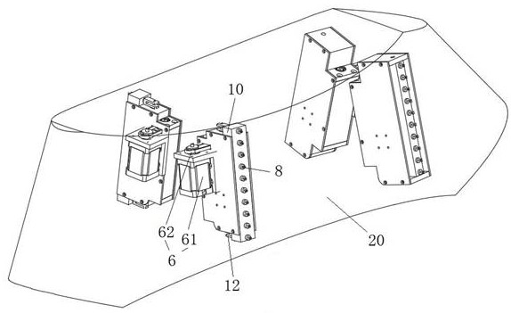
[0063] Such as Figure 1 to Figure 3 As shown, as a further optimization of Embodiment 1 and Embodiment 2, this embodiment includes all the technical features of Embodiment 1 and Embodiment 2, and this embodiment provides a propeller hub.
[0064] A propeller hub includes the telescopic vortex generator described above.
[0065] Because the propeller hub adopts the above-mentioned telescopic vortex generator. During work, the driving device 6 drives the pivot 1 to make a circular motion on a plane perpendicular to the center line of the pivot 1 axis, and the pivot 1 drives the rotating connecting block 4 to move, and now the rotating connecting block 4 has a function along the axis of the pivot 1. The rotational movement of the plane perpendicular to the center line also has a linear telescopic movement away from or close to the side of the pivot 1 (wherein, the end of the rotating connecting block 4 away from the pivot makes a linear motion, and the end of the rotating conne...
PUM
 Abstract
Description
Claims
Application Information
 - R&D Engineer
- R&D Manager
- IP Professional
- Industry Leading Data Capabilities
- Powerful AI technology
- Patent DNA Extraction
Browse by: Latest US Patents, China's latest patents, Technical Efficacy Thesaurus, Application Domain, Technology Topic, Popular Technical Reports.
© 2024 PatSnap. All rights reserved.Legal|Privacy policy|Modern Slavery Act Transparency Statement|Sitemap|About US| Contact US: help@patsnap.com