Power equipment detection device based on Internet of Things
A technology of electric equipment and detection devices, which is applied in the field of electric equipment detection devices based on the Internet of Things, can solve problems such as fire hazards, aging of circuit harnesses, and inability to effectively reduce the temperature of electric equipment boxes, so as to speed up the aging of lines and improve the safety of use Effect
- Summary
- Abstract
- Description
- Claims
- Application Information
AI Technical Summary
Problems solved by technology
Method used
Image
Examples
Embodiment 1
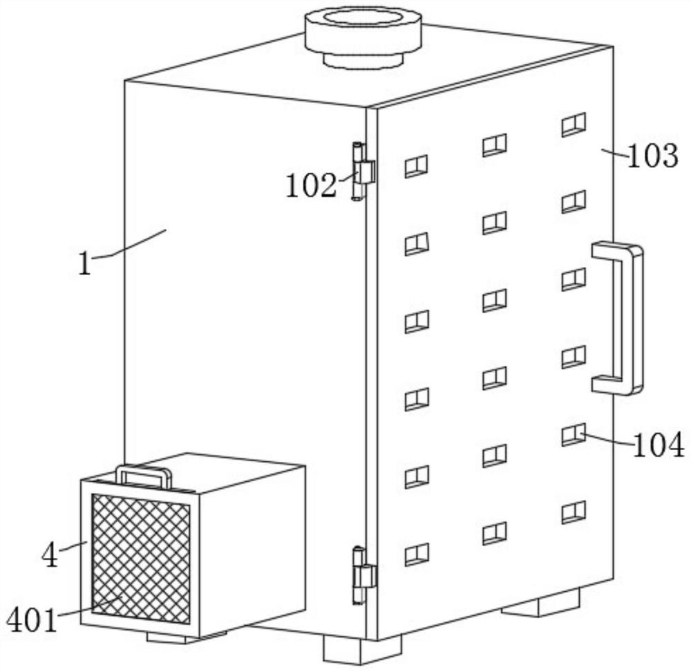
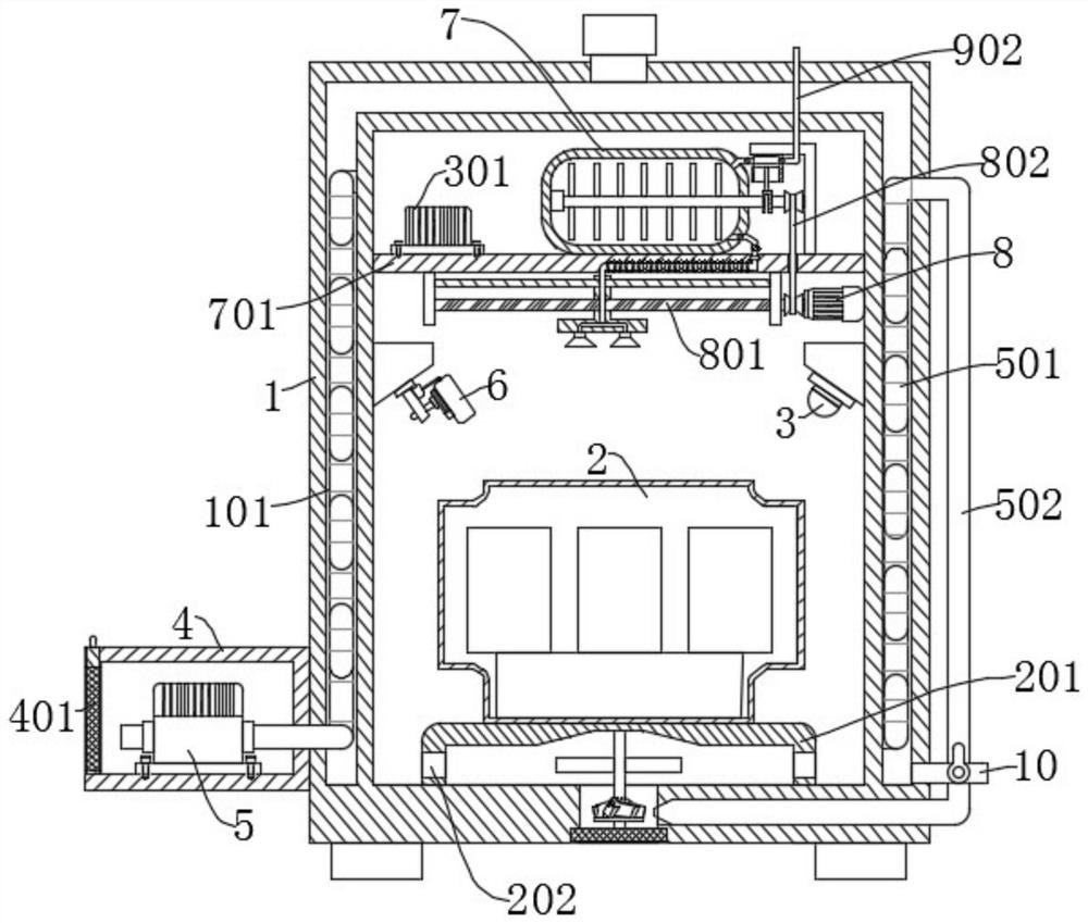
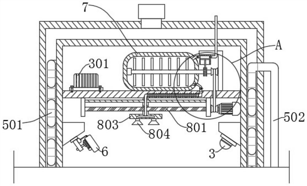
[0033] refer to Figure 1-7 , a power equipment detection device based on the Internet of Things, including a power equipment box 1, also includes: a placement frame 201, fixedly connected to the bottom inner wall of the power equipment box 1; a power equipment body 2, installed on the placement frame 201; a temperature sensor 3 , the thermal imager 6, respectively fixedly connected to both sides of the inner wall of the power equipment box 1; the support plate 701, fixedly connected to the inner wall of the power equipment box 1; the dry powder storage tank 7, the control module 301, all fixedly connected to the support plate 701; the nozzle 804 , slidingly connected to the bottom of the support plate 701, wherein the nozzle 804 communicates with the dry powder storage tank 7 through the second conduit 702, the second conduit 702 is equipped with a solenoid valve 703, and the bottom of the support plate 701 is provided with a drive unit for driving the nozzle 804 to move; The...
Embodiment 2
[0040] refer to image 3 , 5 , a power equipment detection device based on the Internet of Things, which is basically the same as Embodiment 1, and furthermore, the dry powder storage tank 7 is rotatably connected with a rotating shaft 2 705, and the outer wall of the rotating shaft 705 is fixedly connected with a breaking rod 706.
[0041] The crankshaft 9 is fixedly connected to the rotating shaft 2 705, the piston assembly 901 and the motor 8 are respectively fixedly connected to the support plate 701, the piston assembly 901 is connected to the crankshaft 9 in rotation, the piston assembly 901 is connected to the conduit 3 902, and the piston assembly 901 and the dry powder storage Tank 7 is communicated with through conduit 4 903 , and the output end of motor 8 is connected with rotating shaft 2 705 through belt 802 .
[0042] When the motor 8 drives the screw rod 801 to rotate, the motor 8 drives the rotating shaft 2 705 to rotate through the belt 802, and the rotating ...
Embodiment 3
[0044] refer to figure 2 , 6 , a power equipment detection device based on the Internet of Things, which is basically the same as that of Embodiment 1, furthermore, a U-shaped pipe 501 is arranged in the interlayer 101, and a refrigerator 5 is connected to the side wall of the power equipment box 1, and the refrigerator 5 The output end is connected with the inlet end of the U-shaped pipe 501 , and the output end of the U-shaped pipe 501 is connected with the outer wall of the power equipment box 1 .
[0045] The bottom of the power equipment box 1 is provided with an air inlet, and the bottom of the placement frame 201 is rotatably connected with a rotating shaft 503, and the rotating shaft 503 is fixedly connected with fan blades 504 and impellers 505 respectively. 502 is connected, and an activated carbon filter screen 506 is inserted on the air inlet.
[0046] When the temperature sensor 3 gives an alarm when the temperature inside and outside the power equipment box 1 ...
PUM
 Abstract
Description
Claims
Application Information
 - Generate Ideas
- Intellectual Property
- Life Sciences
- Materials
- Tech Scout
- Unparalleled Data Quality
- Higher Quality Content
- 60% Fewer Hallucinations
Browse by: Latest US Patents, China's latest patents, Technical Efficacy Thesaurus, Application Domain, Technology Topic, Popular Technical Reports.
© 2025 PatSnap. All rights reserved.Legal|Privacy policy|Modern Slavery Act Transparency Statement|Sitemap|About US| Contact US: help@patsnap.com


