Material receiving device of numerical control lathe

A material receiving device, CNC lathe technology, applied in metal processing machinery parts, maintenance and safety accessories, metal processing and other directions, can solve the problems of increasing production processes and human resources, affecting production safety, scratching workers, etc., to reduce The effect of production process and human resources, security and high efficiency

Inactive Publication Date: 2021-12-21
蒋飞杨
View PDF0 Cites 0 Cited by
  • Summary
  • Abstract
  • Description
  • Claims
  • Application Information

AI Technical Summary

Problems solved by technology

When the parts are turned, the iron wires after turning are often sleeved on the outer surface of the parts. In the cutting process, the finished parts fall into the CNC lathe just like the chips after cutting. At this time, the outer surface of the parts Several layers of iron wire will be socketed. In order to carry out the next processing procedure of the part, a special person is required to remove the outer layer of iron wire, which will increase the production process and human resources, and the manual removal method is inefficient. The iron wire after turning is sharper and has It may scratch workers and affect the safety of production

Method used


Image

  • Material receiving device of numerical control lathe
  • Material receiving device of numerical control lathe
  • Material receiving device of numerical control lathe

Examples


Embodiment Construction

[0023] use Figure 1-Figure 7 A material receiving device of a numerically controlled lathe according to an embodiment of the present invention is described as follows.

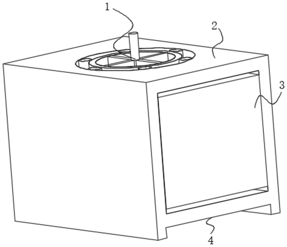
[0024] Such as Figure 1-Figure 7 As shown, a material receiving device of a numerically controlled lathe according to the present invention includes a box body 2, the top of the box body 2 is provided with an inlet, and the top of the box body 2 is connected with a rotating shaft through the inlet. Drum 1, the outer surface of the drum 1 is slidingly connected to the inner wall of the box body 2, both sides of the box body 2 are fixedly connected with baffles 3, and the bottom end of the box body 2 is fixedly connected with an opening plate 4 , the outer surface of the opening plate 4 is fixedly connected to the bottom end of the inner wall of the box body 2. Before the device works, the top of the rotating cylinder 1 is connected to the power source of the machine tool, so that the rotating cylinder 1 can ...


PUM


Abstract

The invention belongs to the field of numerical control machine tools, and particularly relates to a material receiving device of a numerical control lathe. The material receiving device comprises a box body, the top end of the box body is provided with a material inlet, the top end of the box body is rotatably connected to a rotary drum through the material inlet, the outer surface of the rotary drum is slidably connected to the inner wall of the box body, the two sides of the box body are fixedly connected to baffles, the bottom end of the box body is fixedly connected to an open plate, and the outer surface of the open plate is fixedly connected to the bottom end of the inner wall of the box body. Under the action of force, iron wires are pulled apart by a rotating ball, part of the iron wires separated from the parts are swept out of the rotating drum under the action of a partition plate set, then the parts and the iron wire scraps are separated, the iron wires on the outer layer do not need to be manually removed in the whole machining process, production procedures and manpower resources are reduced, compared with manual iron wire scrap removal, the removing method of the device is high in efficiency and high in practicability, moreover, the production safety can be effectively guaranteed, and the production accident that people are possibly injured by iron wire scraps when the iron wire scraps are removed is avoided.

Description

technical field [0001] The invention belongs to the field of numerically controlled machine tools, in particular to a material receiving device for numerically controlled lathes. Background technique [0002] With the advancement of digital control technology, the precision and automation of CNC machine tools are getting higher and higher. CNC lathes are one of the most widely used CNC machine tools. The CNC machine tool automatically processes the processed parts according to the pre-programmed processing program. CNC lathes have high automation and processing efficiency, easy to guarantee product quality, and greatly reduced labor costs. When the parts are turned, the iron wires after turning are often sleeved on the outer surface of the parts. In the cutting process, the finished parts fall into the CNC lathe just like the chips after cutting. At this time, the outer surface of the parts Several layers of iron wire will be socketed. In order to carry out the next proce...

Claims


Application Information

Patent Timeline
Patent Type & Authority Applications(China)
IPC IPC(8): B23Q7/00B23Q11/00
CPCB23Q7/00B23Q11/0042
Inventor 蒋飞杨
Owner 蒋飞杨
Why Eureka
Try Eureka