Fingerprint identification device and forming method thereof

A fingerprint recognition, convex lens technology, applied in character and pattern recognition, instruments, computer parts and other directions, can solve the problem that the structure of the optical fingerprint recognition device needs to be improved, etc.

Pending Publication Date: 2021-12-17
SHANGHAI OXI TECH
View PDF0 Cites 0 Cited by
  • Summary
  • Abstract
  • Description
  • Claims
  • Application Information

AI Technical Summary

Problems solved by technology

[0006] However, the structure of the existing optical fingerprint identification device still needs to be improved.

Method used


Image

  • Fingerprint identification device and forming method thereof
  • Fingerprint identification device and forming method thereof
  • Fingerprint identification device and forming method thereof

Examples


Embodiment Construction

[0033] It can be seen from the background technology that the structure of the existing fingerprint identification device still needs to be improved.

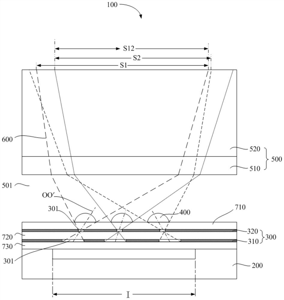
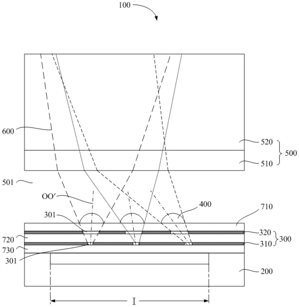
[0034] Now analyze a fingerprint identification device, the fingerprint identification device includes: a photosensitive layer, the surface of the photosensitive layer has a horizontal pixel area; an aperture layer is located on the photosensitive layer, and the aperture layer has a plurality of A diaphragm hole; a convex lens group, located on the diaphragm layer and projected toward the photosensitive layer in the pixel area, the convex lens group includes a plurality of convex lenses, and the convex lenses correspond to the diaphragm hole, The projection of the center of the bottom surface of the convex lens toward the diaphragm layer coincides with the corresponding center of the diaphragm hole.

[0035] The convex lens and the corresponding aperture constitute a focusing and collimating unit. The photosensitive layer in t...


PUM

PropertyMeasurementUnit
Thicknessaaaaaaaaaa

Abstract

The invention discloses a fingerprint identification device and a forming method thereof, and the device comprises: a photosensitive layer, wherein the surface of the photosensitive layer is provided with a transverse pixel region; a diaphragm layer, wherein the diaphragm layer is located on the photosensitive layer, and the diaphragm layer is provided with a plurality of diaphragm holes; a convex lens group, wherein the convex lens group is located on the diaphragm layer, the projection, facing the photosensitive layer, of the convex lens group is located in the pixel area, the convex lens group comprises a plurality of convex lenses, the convex lenses correspond to the diaphragm holes, the center of the bottom face of each convex lens and the center of the corresponding diaphragm hole form a sub-view-field center axis, projections of any two sub view field central axes belonging to the same pixel area on at least one vertical plane intersect, and an intersection point is located above the convex lens group. The fingerprint identification device can improve the image resolution and improve the fingerprint imaging definition, in addition, the risk of optical crosstalk can be reduced, and the imaging quality is further improved.

Description

technical field [0001] The invention relates to the technical field of fingerprint identification, in particular to a fingerprint identification device and a forming method thereof. Background technique [0002] The fingerprint identification device can realize the automatic collection of fingerprints, and is widely used in attendance machines, access control, mobile phones or tablet computers and other equipment. [0003] According to the principle of fingerprint imaging, fingerprint recognition devices can be divided into optical fingerprint recognition devices, semiconductor capacitive recognition devices, semiconductor thermal recognition devices, semiconductor pressure sensitive recognition devices, etc. [0004] Among them, the optical fingerprint recognition device mainly uses the principle of refraction and reflection of light. The light emitted by the light source is refracted on the uneven lines of the fingerprint on the surface of the finger and the light reflecte...

Claims


Application Information

Patent Timeline
IPC IPC(8): G06K9/00
Inventor 凌严朱虹
Owner SHANGHAI OXI TECH
Why Eureka
Try Eureka