
Miniature laser detection device and control method thereof

A laser detection and miniature technology, which is applied in the field of laser detection, can solve the problems of multi-wiring space, unfavorable miniaturization design of laser detection devices, and large volume, and achieve the effect of improving circuit integration

Pending Publication Date: 2021-12-17
HUBEI SANJIANG AEROSPACE WANFENG TECH DEV
View PDF0 Cites 0 Cited by
  • Summary
  • Abstract
  • Description
  • Claims
  • Application Information

AI Technical Summary

Problems solved by technology

However, since the amplification circuits of the four signals are completely independent, their volume is relatively large, which takes up a lot of wiring space, which is not conducive to the miniaturization design of the laser detection device.

Method used


Image

  • Miniature laser detection device and control method thereof
  • Miniature laser detection device and control method thereof
  • Miniature laser detection device and control method thereof

Examples


Embodiment 1

[0059] This embodiment describes the device in conjunction with a specific circuit structure.

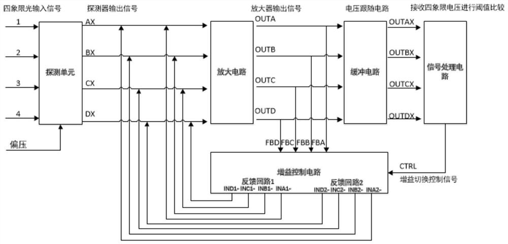
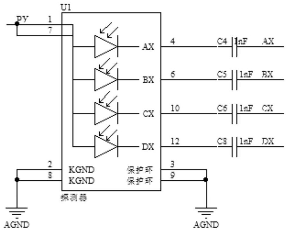
[0060] Such as figure 2 As shown, the four-quadrant detector converts the optical signal into an electrical signal through U1, and outputs four voltage signals AX, BX, CX, DX to the amplifier circuit through the output terminal.

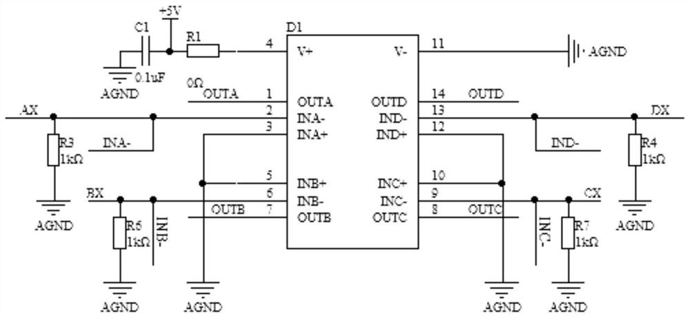
[0061] Such as image 3 As shown, the low-power amplifier D1 of the amplifying circuit is provided with 4 signal input terminals, which respectively receive AX, BX, CX, DX signals, and simultaneously receive corresponding gain signals INA-, INB-, INC-, IND -. D1 realizes the amplified output of the signal according to the input voltage signal and gain signal, and its output signals OUTA, OUTB, OUTC, and OUTD are input to each corresponding inverse proportional operation feedback loop.

[0062] Such as Figure 4 As shown, the gain control module uses a low-impedance analog switch chip D2, D2 receives the control signal CTRL, through the high / low level ...

Embodiment 2

[0082] Such as Figure 8 As shown, D2 of the gain control module in this embodiment adopts a four-channel single-pole double-throw analog switch chip, and the chip adopts two inputs and one output. If one of the inputs is connected to the output, the other input is disconnected. Determine which input is connected to the output by controlling the high and low levels of the IN pin, thereby controlling the gain multiple (you can also use this method to achieve single-pole multi-throw, etc., to control more gain multiples). A four-channel single-pole double-throw analog switch chip can perform synchronous control of the gain switching of the four quadrant output signals of the detector.

[0083] The EN# of the four-channel single-pole double-throw analog switch chip is the chip enable signal pin, which is active at low level. Grounding this signal will make the chip work normally when it is powered on; IN is the control signal input pin selected by different channels. Select the ...


PUM

PropertyMeasurementUnit
Resistanceaaaaaaaaaa

Abstract

The invention relates to the technical field of laser detection, in particular to a miniature laser detection device and a control method thereof. The device comprises a four-quadrant detector, an amplification circuit, reverse proportional operation feedback loops, a gain control module and a signal processing module. Each reverse proportional operation feedback loop comprises a first feedback loop and a second feedback loop which are arranged in parallel. The reverse proportional operation feedback loops are used for feeding back each path of amplification signals output by the amplification circuit to the gain control module through the first feedback loops or the second feedback loops. The gain control module is used for calculating a corresponding gain signal according to each path of feedback signals and inputting each path of gain signals to the amplification circuit. The signal processing module is used for controlling the gain control module to switch on the first feedback loops or the second feedback loops of the reverse proportion operation feedback loops according to the magnitude of the acquired voltage. The high integration of the amplification circuit can be realized, and the miniaturization design of the laser detection device becomes possible.

Description

technical field [0001] The invention relates to the technical field of laser detection, in particular to a miniature laser detection device and a control method thereof. Background technique [0002] Laser semi-active guidance has the characteristics of high precision, strong anti-interference ability, relatively simple structure, low cost, and convenient use, and can be widely used in actual combat. The miniaturization of laser detection devices has always been an important development direction in the military field of various countries, and has broad development prospects. [0003] For the four-way signal output of the four-quadrant detector, the existing laser detection device adopts four amplification circuits to respectively amplify and process the signals of the four-quadrant detector. However, since the amplifying circuits of the four signals are completely independent, they are large in size and occupy a lot of wiring space, which is not conducive to the miniaturiz...

Claims


Application Information

Patent Timeline
IPC IPC(8): G01V8/10F41G3/06
CPCG01V8/10F41G3/065
Inventor 胡冬粤周辉冯建凡张正洋栾庆辉
Owner HUBEI SANJIANG AEROSPACE WANFENG TECH DEV
Learn More