Uninterruptible power source circuit and control method thereof
A technology of power circuit and inductance, which is applied in the field of communication, can solve the problems of large charger, low integration, large overall UPS volume, etc., and achieve the effect of simplifying the circuit structure, improving the circuit integration, and reducing the volume of the whole machine
- Summary
- Abstract
- Description
- Claims
- Application Information
AI Technical Summary
Problems solved by technology
Method used
Image
Examples
Embodiment 1
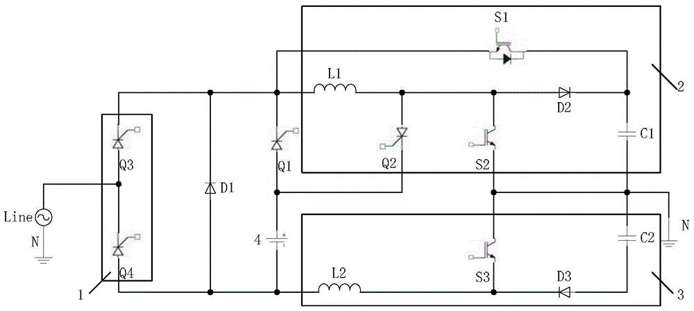
[0041] see Picture 1-1 , the embodiment of the present invention provides a UPS circuit, including:
[0042] AC input module 1, positive boost module 2, negative boost module 3, battery 4, first switching tube S1, first thyristor Q1, second thyristor Q2 and first diode D1;
[0043] The AC input module 1 is used to convert the mains power into a DC voltage. The positive Boost boost module 2 is connected to the AC input module 1. The positive Boost boost module 2 is used to output the AC input module 1 in the positive half cycle of the mains power. The DC voltage is boosted, and the negative Boost boost module 3 is connected to the AC input module 1. The negative Boost boost module 3 is used to boost the DC voltage output by the AC input module 1 in the negative half cycle of the mains power. The first The thyristor Q1 is used to selectively connect the AC input module 1 and the battery 4 to the positive Boost boost module 2 or the negative Boost boost module 3;
[0044] The c...
Embodiment 2
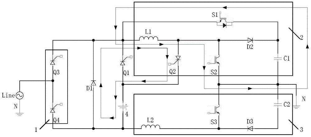
[0068] An embodiment of the present invention provides a method for controlling a UPS circuit, which can control any of the UPS circuits provided in the above embodiments, see figure 2 , the method includes:
[0069] Step 201: Control the conduction of the first switch tube, so that the first output filter capacitor in the positive boost module outputs current to the first inductor in the positive boost module, so that the first inductor stores energy;
[0070] Step 202: Control the first switching tube to turn off, discharge the first inductor in the positive boost module and charge the battery through the second thyristor and the first diode.
[0071] Preferably, the above step 201 may be:
[0072] Control the conduction of the first switch tube, so that the current in the first output filter capacitor in the positive Boost boost module flows into the neutral of the mains through the first switch tube, the first inductor and the second switch tube in the positive Boost boo...
Embodiment 3
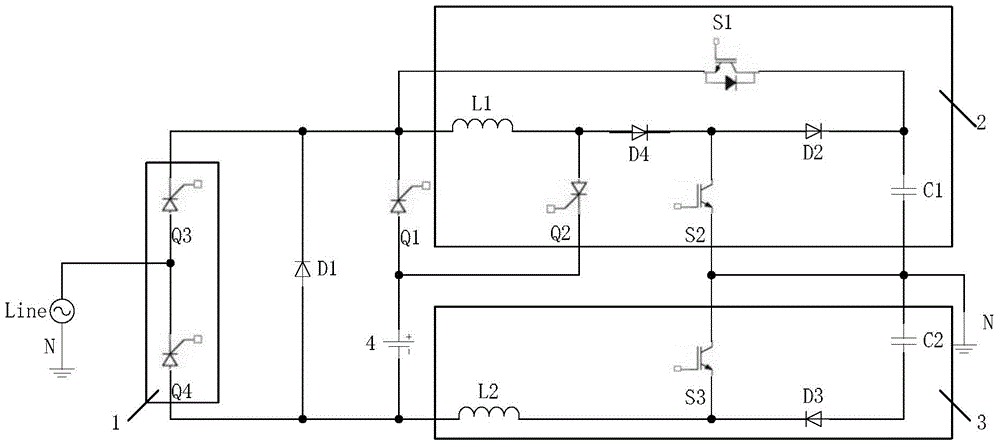
[0078] see Figure 3-1 , the embodiment of the present invention provides a UPS circuit, including:
[0079] AC input module 1, positive boost module 2, negative boost module 3, battery 4, first switching tube S1, first thyristor Q1, second thyristor Q2 and first diode D1;
[0080] The AC input module 1 is used to convert the mains power into a DC voltage. The positive Boost boost module 2 is connected to the AC input module 1. The positive Boost boost module 2 is used to output the AC input module 1 in the positive half cycle of the mains power. The DC voltage is boosted, and the negative Boost boost module 3 is connected to the AC input module 1. The negative Boost boost module 3 is used to boost the DC voltage output by the AC input module 1 in the negative half cycle of the mains power. The first The thyristor Q1 is used to selectively connect the AC input module 1 and the battery 4 to the positive Boost boost module 2 or the negative Boost boost module 3;
[0081] The e...
PUM
 Abstract
Description
Claims
Application Information
 - R&D
- Intellectual Property
- Life Sciences
- Materials
- Tech Scout
- Unparalleled Data Quality
- Higher Quality Content
- 60% Fewer Hallucinations
Browse by: Latest US Patents, China's latest patents, Technical Efficacy Thesaurus, Application Domain, Technology Topic, Popular Technical Reports.
© 2025 PatSnap. All rights reserved.Legal|Privacy policy|Modern Slavery Act Transparency Statement|Sitemap|About US| Contact US: help@patsnap.com


