
Optical fiber temperature sensor

A fiber optic sensor and fiber optic temperature technology, applied in thermometers, thermometer parts, thermometers with physical/chemical changes, etc., can solve the problems of no fiber optic sensor protection measures, fiber optic sensor damage, and fiber optic sensor without effective protection. , to achieve the effect of convenient and fast movement, preventing data loss and preventing pipeline overheating

Inactive Publication Date: 2021-12-17
邢程
View PDF0 Cites 0 Cited by
  • Summary
  • Abstract
  • Description
  • Claims
  • Application Information

AI Technical Summary

Problems solved by technology

[0004] There are multiple optical fiber sensors on the pipeline of the thermal system to monitor the temperature change and vibration information of the mechanical devices in the thermal system in real time. However, there is no effective protection for these optical fiber sensors. When the thermal pipeline is overheated and partially blocked, resulting in local overheating, Optical fiber sensors are easily damaged by overheating, and there are no protective measures for optical fiber sensors on current thermal pipelines

Method used


Image

  • Optical fiber temperature sensor
  • Optical fiber temperature sensor
  • Optical fiber temperature sensor

Examples


Embodiment 1

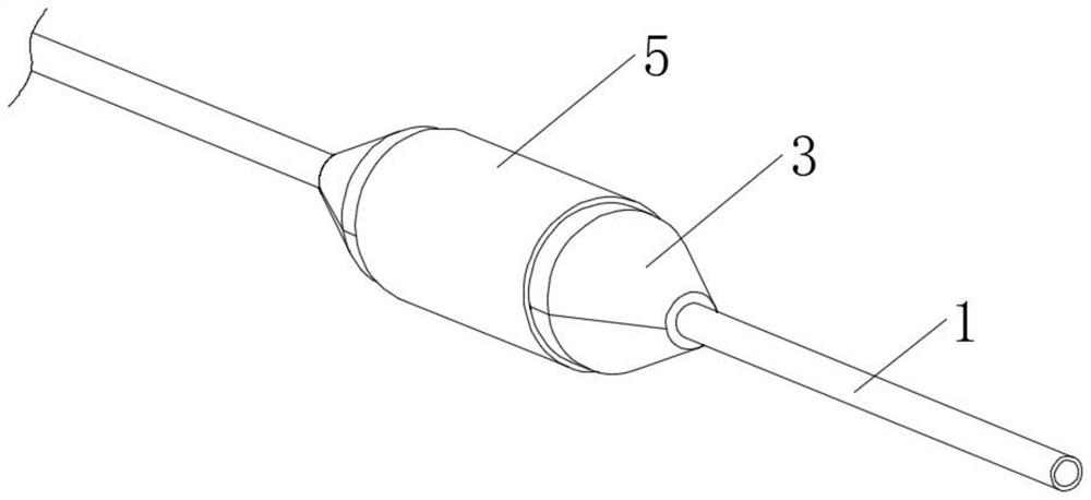
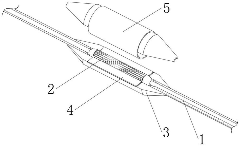
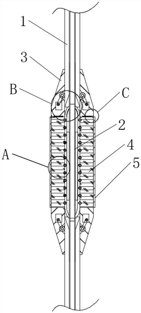
[0042] see Figure 1-6 , an optical fiber temperature sensor, comprising a multi-section pipeline main body 1, a plurality of detection sleeves 2 are fixedly connected to the pipeline main body 1, the detection sleeve 2 includes an optical fiber sensor main body 201, and sliding sleeves 202 are fixedly connected to both ends of the optical fiber sensor main body 201, The outer wall of the optical fiber sensor main body 201 is fixedly connected with an annular electric plate 203, and a pair of inspection posts 3 that are engaged with each other are provided on the outside of the detection sleeve 2. There is a rubber cone 302, and a guide wheel 303 is connected with the rotation in the rubber cone 302. A micro motor matching the guide wheel 303 is installed in the rubber cone 302, and a flexible rubber strip 304 is connected between the rubber cone 302 and the semicircular shell 301. One end of the cone 302 close to the semicircular shell 301 is fixedly connected with a magnet p...


PUM


Abstract

The invention discloses an optical fiber temperature sensor, which belongs to the field of optical fiber sensing. The optical fiber temperature sensor comprises a plurality of sections of pipeline main bodies, the pipeline main bodies are fixedly connected with a plurality of optical fiber sensors, the outer sides of the optical fiber sensors are provided with a pair of inspection columns which are clamped with each other, each inspection column comprises a semicircular shell, and the two ends of each semicircular shell are provided with rubber cones; a guide wheel is rotatably connected in the rubber cone, a micro motor matched with the guide wheel is installed in the rubber cone, the outer side of the semicircular shell is sleeved with a protection ring, a circuit board matched with the detection sleeve is connected between the pair of inspection columns, and the pair of inspection columns are both connected with the circuit board in a clamped mode.By installing a plurality of optical fiber sensors equidistantly on the pipeline, the detection device circularly moving on the pipeline performs data management on the plurality of optical fiber sensors, and when the pipeline is overheated, the detection device can perform protection and data storage on the optical fiber sensors in time.

Description

technical field [0001] The invention relates to the field of optical fiber sensing, in particular to an optical fiber temperature sensor. Background technique [0002] The operating environment of buried thermal pipelines is relatively complex, where there are water, corrosion, high temperature, high stress, and strong electromagnetic fields. In the distributed optical fiber temperature measurement and vibration measurement technology, the optical fiber is both a sensor and a signal transmission medium, so it is very important to choose a suitable sensing optical fiber for the complex environment of the thermal pipeline. The carbon-sealed coated optical fiber currently used for submarine cables can be used in power plants, seabeds, oil fields, natural gas wells, etc. where there is a large amount of water, hydrogen, corrosion, high temperature and pressure, high stress, and strong electromagnetic fields. It uses optical fiber sensing technology to replace traditional electr...

Claims


Application Information

Patent Timeline
Patent Type & Authority Applications(China)
IPC IPC(8): G01K11/32G01K1/12G01K1/14
CPCG01K11/32G01K1/12G01K1/14
Inventor 邢程
Owner 邢程
Learn More