Automatic nut pushing device for mechanical assembly

A technology for pushing devices and nuts, which is applied in metal processing equipment, metal processing, manufacturing tools, etc. It can solve the problems of reduced work efficiency, nuts are easy to block the lower barrel, and increase labor intensity, so as to improve work efficiency and increase stability. sex, efficiency-enhancing effect

Active Publication Date: 2021-12-17
JIANGXI COLLEGE OF APPLIED TECH
View PDF6 Cites 2 Cited by
  • Summary
  • Abstract
  • Description
  • Claims
  • Application Information

AI Technical Summary

Problems solved by technology

[0005] In order to overcome the shortcomings of the traditional mechanical nut pushing equipment, the appropriate height cannot be adjusted according to the length of the bolt, which increases the labor intensity and affects the assembly progress of the machine. Technical problem: Provide an automatic nut pushing device for mechanical assembly that can be adjusted according to the length of the bolt and can be shaken and unloaded

Method used


Image

  • Automatic nut pushing device for mechanical assembly
  • Automatic nut pushing device for mechanical assembly
  • Automatic nut pushing device for mechanical assembly

Examples


Embodiment 1

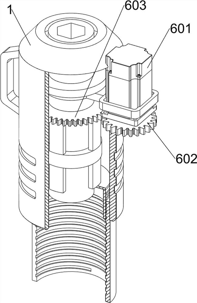
[0037] An automatic nut pushing device for mechanical assembly, such as Figure 1-Figure 9 As shown, it includes a casing 1, a first start button 2, a second start button 3, a third start button 4, a driving assembly 6, a clamping assembly 7 and a limit assembly 8, and the upper front side of the casing 1 is installed with a first start button. Button 2, the second start button 3 is installed on the front side of the upper part of the shell 1, and the second start button 3 is located below the first start button 2, and the third start button 4 is installed on the front side of the upper part of the shell 1, and the third start button 4 is located on the second Below the start button 3 , the housing 1 is provided with a driving assembly 6 , and the inner lower side of the driving assembly 6 is connected with a clamping assembly 7 , and a limiting assembly 8 is installed between the clamping assembly 7 and the driving assembly 6 .

[0038]The driving assembly 6 also includes a f...

Embodiment 2

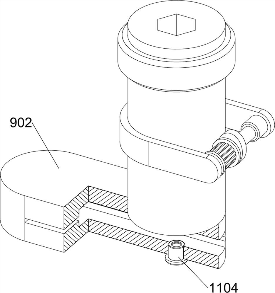
[0043] On the basis of Example 1, such as Figure 10-Figure 17 As shown, the blanking assembly 9 is also included, and the blanking assembly 9 also includes a blanking chute 901, a connecting block 902, an electromagnet 903, a metal block 904, a third slide bar 905, a third spring 906 and a pushing block 907, A connection block 902 is installed on the top of the casing 1, a feeding chute 901 is arranged on the right side of the top of the connection block 902, an electromagnet 903 is installed on the left side of the connection block 902, and a third slide bar 905 is fixedly connected to the front and rear sides of the connection block 902. A metal block 904 is slidably connected between the right side of the slide bar 905, and the metal block 904 and the electromagnet 903 are attracted to each other. A third spring 906 is connected between the metal block 904 and the third slide bar 905, and the third spring 906 is wound around On the third slide bar 905 , a pushing block 907...


PUM


Abstract

The invention relates to a pushing device, in particular to an automatic nut pushing device for mechanical assembly. The technical problem to be solved is to provide the automatic nut pushing device for mechanical assembly, which can be adjusted according to the length of a bolt and can perform shaking discharging. The automatic nut pushing device for mechanical assembly comprises a shell, a first starting key, a second starting key and a third starting key; the first starting key is arranged on one side of the upper part of the shell; the second starting key is arranged on the side, close to the first starting key, of the upper part of the shell; and the third starting key is arranged on the side, close to the second starting key, of the upper part of the shell. A pushing block moves leftwards, a nut can be pushed leftwards into a limiting groove, in this way, the effect of automatically pushing the nut is achieved, a sliding block moves up and down according to the length of the bolt, an adjusting block is driven to move up and down to adjust the proper height, and the effect of adjusting the height of a spiral groove is achieved.

Description

technical field [0001] The invention relates to a pushing device, in particular to an automatic nut pushing device for mechanical assembly. Background technique [0002] With the continuous development of the machinery industry, more and more mechanical equipment has appeared. Most of the mechanical assembly is one of the important links to fix the mechanical parts through the cooperation between nuts and bolts. [0003] Traditional mechanical nut pushing equipment generally cannot adjust the appropriate height according to the length of the bolts for nut tightening work. While increasing the labor intensity, it will also affect the progress of the mechanical assembly, and the nuts are easily blocked in the lower barrel, requiring manual work. Shaking the lower material barrel makes the nuts unloaded, which brings inconvenience to people's use and reduces work efficiency. [0004] To sum up, it is necessary to design an automatic nut pushing device for mechanical assembly t...

Claims


Application Information

Patent Timeline
Patent Type & Authority Applications(China)
IPC IPC(8): B23P19/06
CPCB23P19/001B23P19/06
Inventor 罗国虎郭金妹廖强张建荣
Owner JIANGXI COLLEGE OF APPLIED TECH
Why Eureka
Try Eureka