
Aircraft accumulated ice shape simulation method and device, computer equipment and storage medium

A simulation method and aircraft technology, applied in computer equipment and storage medium, aircraft icing and ice shape simulation method, and device field, can solve problems such as gap, high learning cost, influence on the accuracy of calculation results, etc., and achieve precise simulation and low error reporting probability. Effect

Active Publication Date: 2021-12-14
NAT UNIV OF DEFENSE TECH
View PDF2 Cites 1 Cited by
  • Summary
  • Abstract
  • Description
  • Claims
  • Application Information

AI Technical Summary

Problems solved by technology

At present, some domestic researchers use the steady-state method to simulate the ice accumulation problem on the aircraft surface. However, the ice accumulation on the aircraft surface is a dynamic process, and the ice shape will continue to change with the ice accumulation time. Therefore, there are differences between the steady-state method and the actual ice accumulation. gap
In addition, the ice shape on the surface of the aircraft is complex and irregular, and different ice shapes have a great influence on the aerodynamic characteristics of the aircraft surface
However, in some existing studies, the ice shape is classified into types such as blunt body, bihedron, and pointed body to simplify the problem. After the simplification, the combination of ice shape types cannot cover the actual complex ice shape. The accuracy of the results will affect the
At the same time, there are still methods of using NURBS spline curves to fit the shape of ice accretion. Using spline curves can only approximate the ice shape of the entire area smoothly, but cannot achieve a more detailed local ice shape. Sophisticated simulations such as burr-like accretion on wedge-shaped ice surfaces, etc.
Finally, the above methods are mostly implemented with the help of commercial software such as Fluent, etc., and the learning cost is high. Although the functions are complete, the volume is huge. Compared with the more targeted self-programming method, the efficiency is not high

Method used


Image

  • Aircraft accumulated ice shape simulation method and device, computer equipment and storage medium
  • Aircraft accumulated ice shape simulation method and device, computer equipment and storage medium
  • Aircraft accumulated ice shape simulation method and device, computer equipment and storage medium

Examples


Embodiment Construction

[0073] In order to make the purpose, technical solution and advantages of the disclosed invention more clear, the present invention will be further described in detail below in conjunction with specific embodiments and according to the accompanying drawings. It should be noted that, in the drawings or descriptions in the specification, the content not described and some English abbreviations are the content well known to those of ordinary skill in the art. Some specific parameters given in the following examples are only for demonstration, and the values ​​can be correspondingly changed to appropriate values ​​in different implementations.

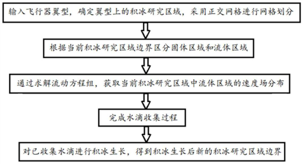
[0074] refer to figure 1 , in order to quickly and accurately describe the shape of ice accretion, an embodiment of the present invention proposes a method for simulating ice accumulation and ice shape of an aircraft, including the following steps:

[0075] S1, input the airfoil of the aircraft, determine the ice accretion research area o...


PUM


Abstract

The invention provides an aircraft accumulated ice shape simulation method and device, computer equipment and a storage medium. The aircraft accumulated ice shape simulation method comprises the following steps: inputting an aircraft airfoil, determining an accumulated ice research area on the aircraft airfoil, performing grid division by adopting an orthogonal grid, and distinguishing a solid area and a fluid area; obtaining velocity field distribution of a fluid area in the current icing research area by solving the flow equation set; inputting water drop information to complete a water drop collection process; carrying out accumulated ice growth on collected water drops obtained in the water drop collection process, enabling accumulated ice to grow along the current boundary in the normal direction, calculating the accumulated ice growth heights of different positions of the ice accumulation research area, updating the boundary of the ice accumulation research area after ice accumulation to obtain new boundary information of the ice accumulation research area after the accumulated ice grows, and depicting the ice shape of the accumulated ice in a refined manner.

Description

technical field [0001] The invention belongs to the field of computational fluid dynamics, and in particular relates to an aircraft ice accumulation and ice shape simulation method, device, computer equipment and storage medium. Background technique [0002] Frequent flight accidents caused by icing have brought about huge losses in personal safety and social property. During the flight of the aircraft, the leading edge of the wing, the air inlet of the engine, the windshield of the nose, and the windward side of various sensor detection instruments are all areas that are prone to ice formation. The aircraft itself flies by the lift generated by the pressure difference between the upper and lower surfaces of the wings. However, due to the existence of ice accumulation, the aerodynamic shape of the aircraft surface has changed, which affects the aerodynamic characteristics of the aircraft. Studies have shown that the aerodynamic characteristics of the clean configuration va...

Claims


Application Information

Patent Timeline
IPC IPC(8): G06F30/15G06F30/28G06F17/11G06F113/08G06F119/14
CPCG06F30/15G06F30/28G06F17/11G06F2113/08G06F2119/14Y02T90/00
Inventor 田正雨杨帆谢文佳于航张烨
Owner NAT UNIV OF DEFENSE TECH
Learn More