
Piezoelectric type rainfall sensor transduction structure and installation method thereof

A rain sensor and piezoelectric technology, which is applied in the field of transducer structure of piezoelectric rain sensor, can solve the problems of weak output signal, inaccurate measurement of small rain, and inability to take into account the measurement of heavy rain and small rain at the same time.

Pending Publication Date: 2021-12-14
CHINA ELECTRONICS TECH GRP CORP CHONGQING ACOUSTIC OPTIC ELECTRONICS CO LTD
View PDF1 Cites 0 Cited by
  • Summary
  • Abstract
  • Description
  • Claims
  • Application Information

AI Technical Summary

Problems solved by technology

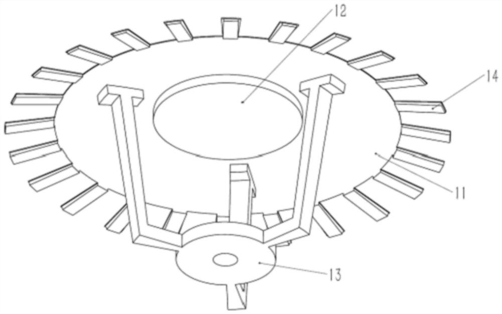
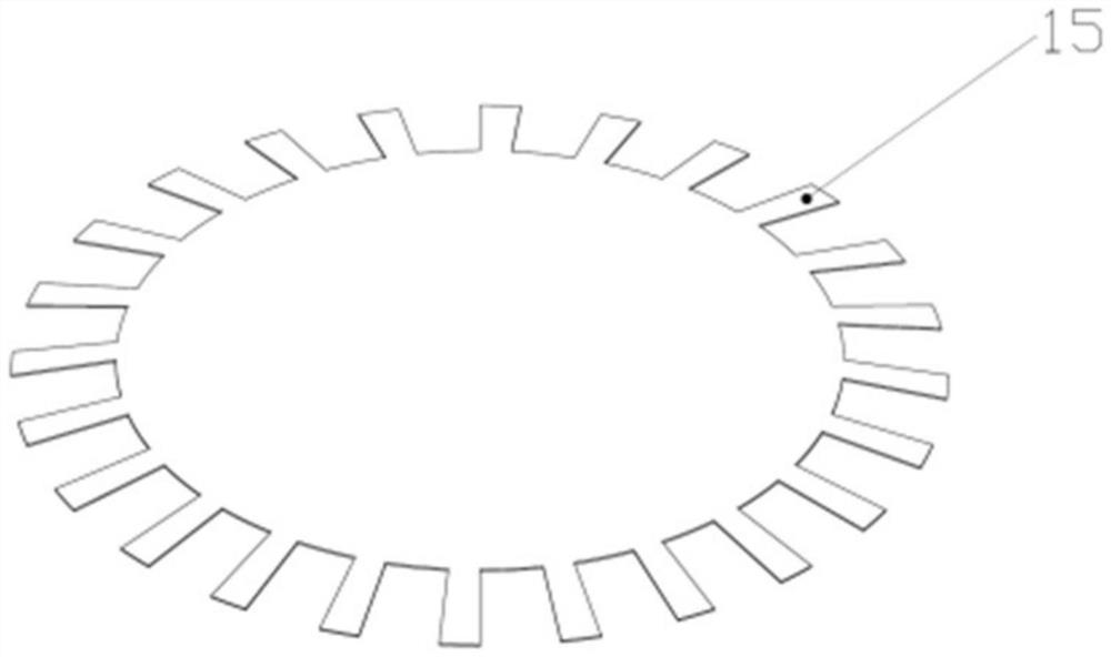
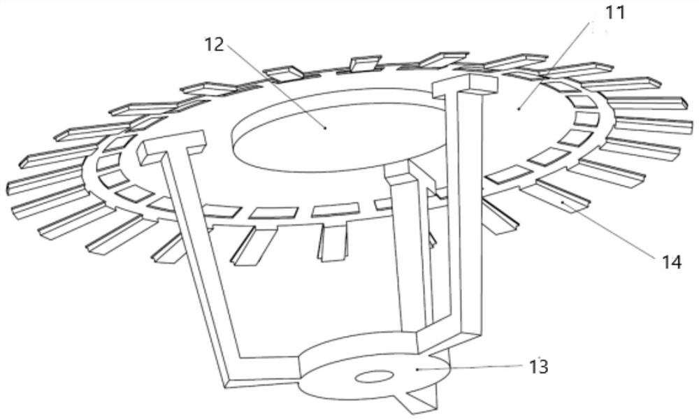
[0004] In order to solve the technical problems that the output signal of the transduction structure of the traditional piezoelectric rain sensor is weak under small rainfall, the measurement of small rainfall is inaccurate, and the measurement of large rainfall and small rainfall cannot be taken into account at the same time, the present invention provides a piezoelectric rain sensor The transducer structure and installation method thereof, the transducer structure includes a housing 11, a circular piezoelectric sheet 12, a bracket 13 and a rectangular piezoelectric sheet 14, the periphery of the housing 11 is provided with a sheet-like cantilever structure 15, the housing 11 There is a concave surface at the center, the circular piezoelectric sheet 12 is bonded to the concave surface of the center of the housing 11, the front and back sides of the cantilever structure 15 are bonded to the rectangular piezoelectric sheet 14, and the bracket 13 is fixed below the housing 11;

Method used


Image

  • Piezoelectric type rainfall sensor transduction structure and installation method thereof
  • Piezoelectric type rainfall sensor transduction structure and installation method thereof
  • Piezoelectric type rainfall sensor transduction structure and installation method thereof

Examples


Embodiment Construction

[0029] The following will clearly and completely describe the technical solutions in the embodiments of the present invention with reference to the accompanying drawings in the embodiments of the present invention. Obviously, the described embodiments are only some, not all, embodiments of the present invention. Based on the embodiments of the present invention, all other embodiments obtained by persons of ordinary skill in the art without making creative efforts belong to the protection scope of the present invention.

[0030] The invention provides a transducer structure of a piezoelectric rain sensor, such as figure 1 As shown, it includes a housing 11, a circular piezoelectric piece 12, a bracket 13 and a rectangular piezoelectric piece 14. A sheet-like cantilever structure 15 is arranged around the housing 11. There is a concave surface at the center of the housing 11. The circular piezoelectric piece 12 is bonded to the concave surface of the housing 11, both sides of th...


PUM


Abstract

The invention relates to the technical field of meteorological monitoring rainfall in a meteorological station, in particular to a piezoelectric type rainfall sensor transduction structure and an installation method thereof. The piezoelectric type rainfall sensor transduction structure comprises a shell, a circular piezoelectric plate, a support and rectangular piezoelectric plates, wherein a sheet-shaped cantilever structure is arranged on the periphery of the shell, and a concave face is arranged in the center of the shell; the circular piezoelectric plate is adhered to the concave surface of the center of the shell, the rectangular piezoelectric plates are adhered to the two surfaces of the cantilever structure, and the support is fixed below the shell. The central area with high impact resistance and the peripheral cantilever bimorph structure with high sensitivity are designed, so that the problems of weak output signal and insensitivity to small rainfall test of the traditional piezoelectric type rainfall sensor transduction structure under small rainfall are solved, the measurement of large rainfall and small rainfall can be taken into consideration, and the early warning capability of the meteorological instrument and the like on natural disasters such as flood, drought, landslide and the like is further improved.

Description

technical field [0001] The invention relates to the technical field of meteorological monitoring rainfall in weather stations, in particular to an energy conversion structure of a piezoelectric rainfall sensor and an installation method thereof. Background technique [0002] Rainfall is a key element in meteorological observation. Accurate and timely acquisition of rainfall data plays an important role in the prevention and control of natural disasters such as floods, droughts, and landslides. Rain gauges are required for rain observation. At present, the common rain gauge is a piezoelectric rain gauge, also known as a piezoelectric rain sensor, which includes a housing, a piezoelectric sensing element, and a signal acquisition circuit. The piezoelectric rain sensor converts the impact signal of falling raindrops into electrical Signal, by collecting and processing the output signal of the piezoelectric sensing element, the particle size of a single raindrop, as well as the ...

Claims


Application Information

Patent Timeline
IPC IPC(8): G01W1/14
CPCG01W1/14Y02A50/00
Inventor 王登攀李军李小飞何香君张灵舒袁宇鹏王露母江东
Owner CHINA ELECTRONICS TECH GRP CORP CHONGQING ACOUSTIC OPTIC ELECTRONICS CO LTD
Learn More