Hydraulic retractable electromechanical equipment auxiliary moving component
A technology for mechanical equipment and auxiliary movement, which is applied in the direction of mechanical equipment, supporting machines, machine tables/supports, etc. It can solve the problems of easy collision of electromechanical equipment, inability to use hydraulic retractable moving wheels, and high cost of moving electromechanical mobile equipment. Achieve the effect of avoiding crane operation, low moving cost and avoiding collision
- Summary
- Abstract
- Description
- Claims
- Application Information
AI Technical Summary
Problems solved by technology
Method used
Image
Examples
Embodiment 1
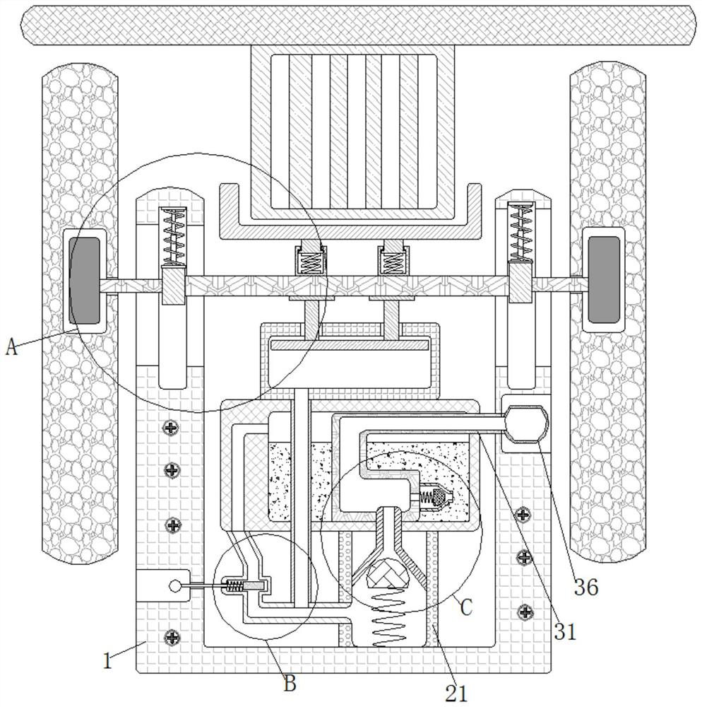
[0025] see Figure 1-4 , a hydraulic retractable electromechanical mechanical equipment auxiliary moving assembly, including a bracket 1, a one-way valve mechanism 2 is arranged on the inside of the bracket 1, and a liquid suction mechanism 3 is arranged on the upper end of the one-way valve mechanism 2 and inside the bracket 1 , the left end of the one-way valve mechanism 2 and the hydraulic control mechanism 4 are arranged inside the bracket 1, the lifting mechanism 5 is arranged on the left end of the bracket 1, and the fixing mechanism 6 is arranged in the middle of the upper end of the bracket 1.
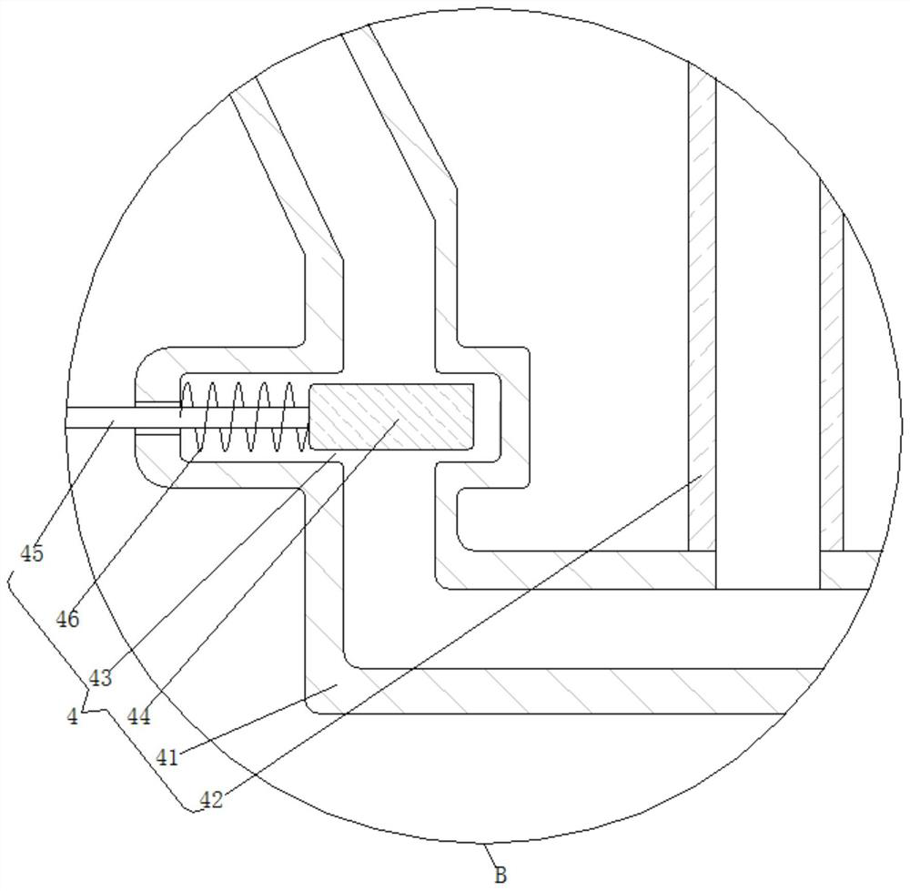
[0026] Further, the left end of the sleeve 21 is fixedly plugged with a pipe 41, the middle of the upper end of the pipe 41 is fixedly plugged with an infusion tube 42, the middle of the pipe 41 is provided with a card slot 43, and the inside of the card slot 43 is movably inserted with a baffle 44, The left end of the baffle plate 44 is fixedly connected with a pull rod 45, an...
Embodiment 2
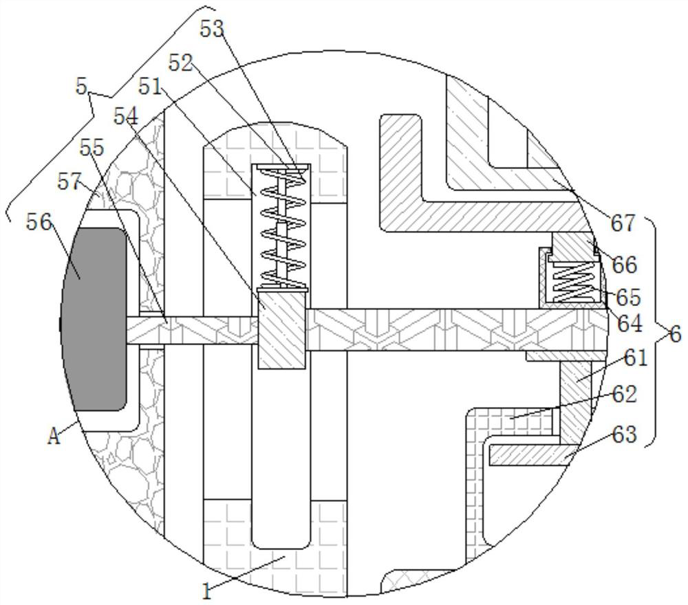
[0031] see Figure 1-4, a hydraulically retractable electromechanical mechanical equipment auxiliary mobile assembly, including a bracket 1, a guide groove 51 is arranged inside the left side wall of the bracket 1, and a telescopic rod 52 is fixedly connected to the upper end of the guide groove 51, and the telescopic rod 52 is located on the outside of the guide groove Adjusting spring 53 is sleeved inside 51, and the lower end of telescopic rod 52 is fixedly connected with slide block 54 inside guide groove 51. The inside of slide block 54 is fixedly inserted with crossbeam 55, and the lower end of crossbeam 55 is fixedly connected with strut 61. The outer side of 61 is movable sleeved with a cylinder 62, the lower end of the strut 61 is fixedly connected with a piston 63 inside the cylinder 62, and the upper end of the beam 55 is fixedly connected with a guide sleeve 64, which can prevent the deflection of the buffer spring 65 during movement , the bottom end of the guide s...
PUM
 Abstract
Description
Claims
Application Information
 - R&D
- Intellectual Property
- Life Sciences
- Materials
- Tech Scout
- Unparalleled Data Quality
- Higher Quality Content
- 60% Fewer Hallucinations
Browse by: Latest US Patents, China's latest patents, Technical Efficacy Thesaurus, Application Domain, Technology Topic, Popular Technical Reports.
© 2025 PatSnap. All rights reserved.Legal|Privacy policy|Modern Slavery Act Transparency Statement|Sitemap|About US| Contact US: help@patsnap.com


