High-speed deep stirring drilling machine and construction method thereof

A technology of deep mixing and drilling rigs, which is applied to drilling equipment and methods, rotary drilling rigs, drill pipes, etc. It can solve the problems of self-locking, short working life, and affecting the construction period, and achieve effective transmission of torque and axial force. , Reduction of moving cost and improvement of working life

Pending Publication Date: 2020-08-25
BEIJING ZHONGYAN DADI TECH CO LTD
View PDF0 Cites 0 Cited by
  • Summary
  • Abstract
  • Description
  • Claims
  • Application Information

AI Technical Summary

Problems solved by technology

The axial force during drilling is transmitted through the friction between the drill pipes, so the transmitted force is unstable, self-locking cannot occur, and retraction occurs during drilling
Especially when encountering hard rock formations, the drilling efficiency is low, or even impossible to drill, which cannot meet the construction requirements
In addition, when the drilling depth reaches a certain depth, water comes out of the well, and some or even most of the drill pipes are soaked in muddy water or mud. The mud enters the gap between the outer slide rail and the inner slide rail of the cylinder, and after repeated extrusion and drying, it becomes thicker and harder to hold. The mud and dirt hinder the smooth sliding of the cylinder, the working life is short, the construction cost is high and the construction period is seriously affected

Method used


Image

  • High-speed deep stirring drilling machine and construction method thereof
  • High-speed deep stirring drilling machine and construction method thereof
  • High-speed deep stirring drilling machine and construction method thereof

Examples


Embodiment Construction

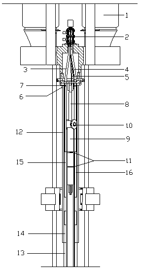
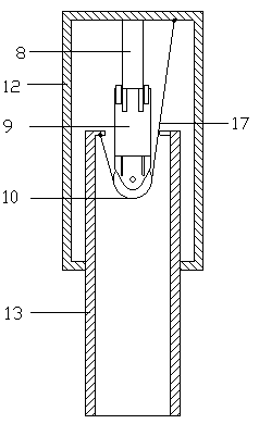
[0032] Below in conjunction with accompanying drawing and specific embodiment the present invention is described in further detail:

[0033] Such as Figure 1~4 Shown, a kind of high-speed deep mixing drilling rig is characterized in that, comprises chassis 20, drilling rig front end, drilling rig background, power system, pile frame, control platform; Described drilling rig background comprises curing agent mixing system, high-pressure gas supply system; The power system includes oil cylinder power system, circular slewing power system, vertical slewing power system, chassis power system, pile frame power system, drilling rig attachment power system; the front end of the drilling rig includes power head 1, rotary joint 2, air pipe 3, and slurry pipe 4 , hydraulic oil pipe 5, exhaust valve 6, constant pressure valve 7, oil cylinder rod 8, oil cylinder barrel 9, pulley 10, oil cylinder guide sleeve 11, outer drill pipe 12, inner drill pipe 13, drill pipe guide sleeve 14, air pipe...


PUM


Abstract

The invention discloses a high-speed deep stirring drilling machine and a construction method thereof, and belongs to the field of pile foundation construction equipment. The high-speed deep stirringdrilling machine comprises a chassis, a drilling machine front end, a drilling machine background, a power system, a pile frame and a control platform, wherein the power system comprises an oil cylinder power system, an annular rotating power system, a vertical rotating power system, a chassis power system, a pile frame power system and a drilling machine accessory power system; an air pipe and aslurry pipe are mounted in an outer drilling rod; a constant-pressure valve is mounted on the side, near a power head, of the air pipe in the outer drilling rod; an exhaust valve is mounted on the outer drilling rod corresponding to the constant-pressure valve; an air pipe sleeve and a slurry pipe sleeve are mounted in an inner drilling rod; pulleys are correspondingly mounted at the top and the bottom of an oil cylinder barrel; a lower steel wire rope is wound on the pulley at the bottom of the oil cylinder barrel; and an upper steel wire rope is wound on the pulley at the top of the oil cylinder barrel. The high-speed deep stirring drilling machine is stable and reliable in pressurization, can be suitable for multiple soil layers and rock layers, reduces the cost, improves the strength and the rigidity of the drilling rods, and prolongs the service life of the drilling rods.

Description

technical field [0001] The invention relates to the field of pile foundation construction equipment, in particular to a high-speed deep-layer mixing drilling machine and a construction method thereof. Background technique [0002] Cast-in-situ piles have low noise and strong adaptability, and are widely used, but the excavation of piles is difficult. In the past, manual excavation has been used, especially in places with limited construction space, such as: tunnels, underground spaces of subway stations, etc. These places Tall machinery cannot be used, only manual and simple mechanical excavation can be used. Manual excavation accidents occur frequently, and excavation is more difficult after dynamic water intrusion into the pile body, and manual excavation is facing being eliminated and banned. When constructing on the ground, how deep the hole needs to be drilled depends on how high the drilling rig tower must be. Usually the depth of drilling is more than 20 meters, and...

Claims


Application Information

Patent Timeline
Patent Type & Authority Applications(China)
IPC IPC(8): E21B7/02E21B7/04E21B19/084E21B3/02E21B17/00E02D5/46
CPCE02D5/46E21B3/02E21B7/02E21B7/04E21B17/00E21B19/084
Inventor 宋伟杰李建平朱庆凯
Owner BEIJING ZHONGYAN DADI TECH CO LTD
Why Eureka
Try Eureka