Optical fiber sensing fabric for pulse and oxyhemoglobin saturation detection and preparation method

An optical fiber sensing and saturation technology, applied in the field of pulse and blood oxygen saturation sensors, can solve problems such as difficult fabric bonding, achieve good contact comfort, improve signal-to-noise ratio, and facilitate mass production.

Pending Publication Date: 2021-12-14
TIANJIN POLYTECHNIC UNIV
View PDF7 Cites 1 Cited by
  • Summary
  • Abstract
  • Description
  • Claims
  • Application Information

AI Technical Summary

Problems solved by technology

In terms of photoplethysmography and blood oxygen saturation detection, current commercial products use semiconductor devices to achieve light emission and light sensitivity, and these devices are difficult to combine with fabrics

Method used


Image

  • Optical fiber sensing fabric for pulse and oxyhemoglobin saturation detection and preparation method
  • Optical fiber sensing fabric for pulse and oxyhemoglobin saturation detection and preparation method
  • Optical fiber sensing fabric for pulse and oxyhemoglobin saturation detection and preparation method

Examples


Embodiment 1

[0039] Embodiment 1: This embodiment demonstrates a preparation method of an optical fiber pulse oximeter sensor fabric based on a weaving process with a microbend convex structure.

[0040] The weft yarn of the optical fiber sensing fabric is made of 1000 μm PMMA polymer optical fiber, the rest of the weft and warp yarns are made of nylon viscose blended yarn, and the light-blocking yarn between the two optical fibers is twisted yarn of 20 nylon viscose blended yarns. The diameter is within 1 to 2mm. Pulse fabric is woven on a dobby loom.

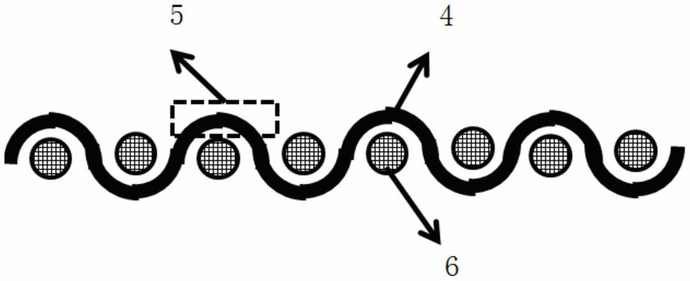
[0041] Both the side-emitting optical fiber and the side-sensitive optical fiber use polymer optical fibers, and a microbend convex structure is formed on the polymer optical fibers by hot pressing.

[0042] Put the polymer optical fiber into the mold with micro-bending grooves, and use the hot air device to heat the polymer optical fiber locally. When the polymer optical fiber in the heating area is softened, it is hot-pressed and solidi...

Embodiment 2

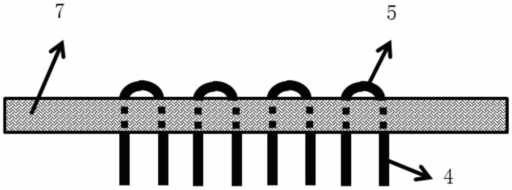
[0048] Embodiment 2: This embodiment demonstrates a preparation method of an optical fiber pulse oximeter sensor fabric based on a laser grooved structure knitting process.

[0049] The optical fiber is a PMMA polymer optical fiber with a diameter of 1000 μm, and the light-blocking yarn is a ply-twisted yarn of 15 or 20 low-elasticity and high-temperature-resistant viscose / nylon yarns, with a diameter of 1 to 2 mm. The remaining yarns are cotton yarns with a fineness of 50 tex / 3.

[0050] The fabric is woven on a warp knitting sample loom, the machine number is E12, the knitting needles are latch needles, and the rear guide frame is used (the yarn does not need to be warped), and the warp is passively let off and directly drawn by the guide frame. Go to the weaving area and weave.

[0051] The overall fabric adopts warp knitted fabric, which has the advantages of stable size, crisp fabric, not easy to fall off, etc. At the same time, it has the characteristics of good air per...


PUM

PropertyMeasurementUnit
Diameteraaaaaaaaaa
Diameteraaaaaaaaaa

Abstract

The invention discloses an optical fiber sensing fabric for pulse and oxyhemoglobin saturation detection and a preparation method. A plurality of side light-emitting optical fibers with side light-emitting units, a plurality of side light-sensing optical fibers with side light-sensing units and common yarns are woven to form the optical fiber fabric, the side light-emitting optical fibers and the side light-sensing optical fibers are alternately arranged, light isolation areas formed by the yarns are arranged between the side light-emitting optical fibers and the side light-sensing optical fibers, the multiple side light-emitting and side light-sensing units form a light-emitting and light-sensing array on the surface of the fabric, so that the collection of red light and infrared band light volume pulse waves and the calculation of blood oxygen saturation are realized. Polymer optical fibers are used as yarns to be woven into the fabric, compared with silicon optical fibers, the flexibility of the fabric can be improved, the polymer optical fibers are intrinsically safe and cannot be broken to hurt people, and the use safety is improved.

Description

technical field [0001] The invention relates to the field of pulse and blood oxygen saturation sensors, in particular to an optical fiber sensing fabric and a preparation method for detecting pulse and blood oxygen saturation. Background technique [0002] Social issues such as population aging, chronic disease prevalence and rejuvenation have prompted people to pay more attention to their own health, and people's demand for telemedicine and home health monitoring has continued to increase, which has fostered a market for the development of wearable health care Base. Wearable sensors facilitate the real-time monitoring of human body information and become the basis and important direction for the development of the big health industry. [0003] Traditional wearable sensors are mostly worn on the human body or clothing as clothing, which has the disadvantages of large size and uncomfortable wearing. To realize the real "wearable" sensor, the fabric sensor is an inevitable c...

Claims


Application Information

Patent Timeline
IPC IPC(8): D03D15/547D03D15/283D04B21/14D05C17/00
CPCD03D15/547D03D15/283D04B21/14D05C17/00D10B2403/0243
Inventor 张诚孙政张美玲赵美玲苗长云赵晓雪
Owner TIANJIN POLYTECHNIC UNIV
Why Eureka
Try Eureka