


Quick Research
Generate reliable direction feasibility study reports for your R&D in just a few steps.

Technical Q&A
Discover and master advanced knowledge NOW. Basics, ideas, possibilities, all at once.

Find Solutions
As an expert in R&D theories, this can generate solutions to your technical problems instantly.

Evaluate Feasibility
Analyze your overall solution with one click, know your potential R&D risks in advance.

Monitor Landscape
Get weekly tech updates, stay abreast of the latest tech innovations and key insights.
Gauze coiling equipment for spinning
A technology of coiling and equipment, which is applied in the direction of coiling strips, sending objects, thin material processing, etc., can solve the problems of low precision, time-consuming and labor-intensive winding work, and low safety, and achieve the effect of high safety
- Summary
- Abstract
- Description
- Claims
- Application Information
AI Technical Summary
Problems solved by technology
Method used
Image

Examples
Embodiment 1
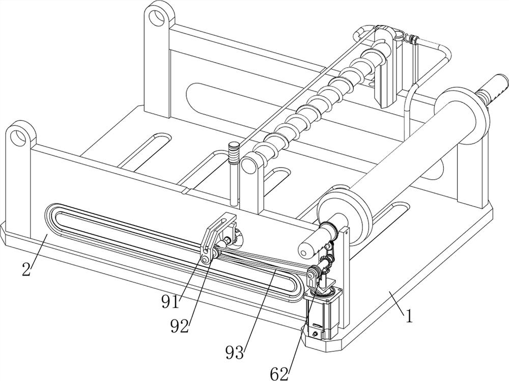
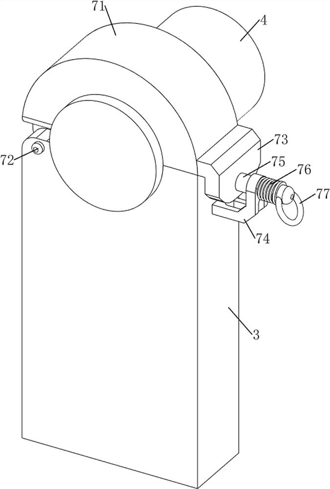
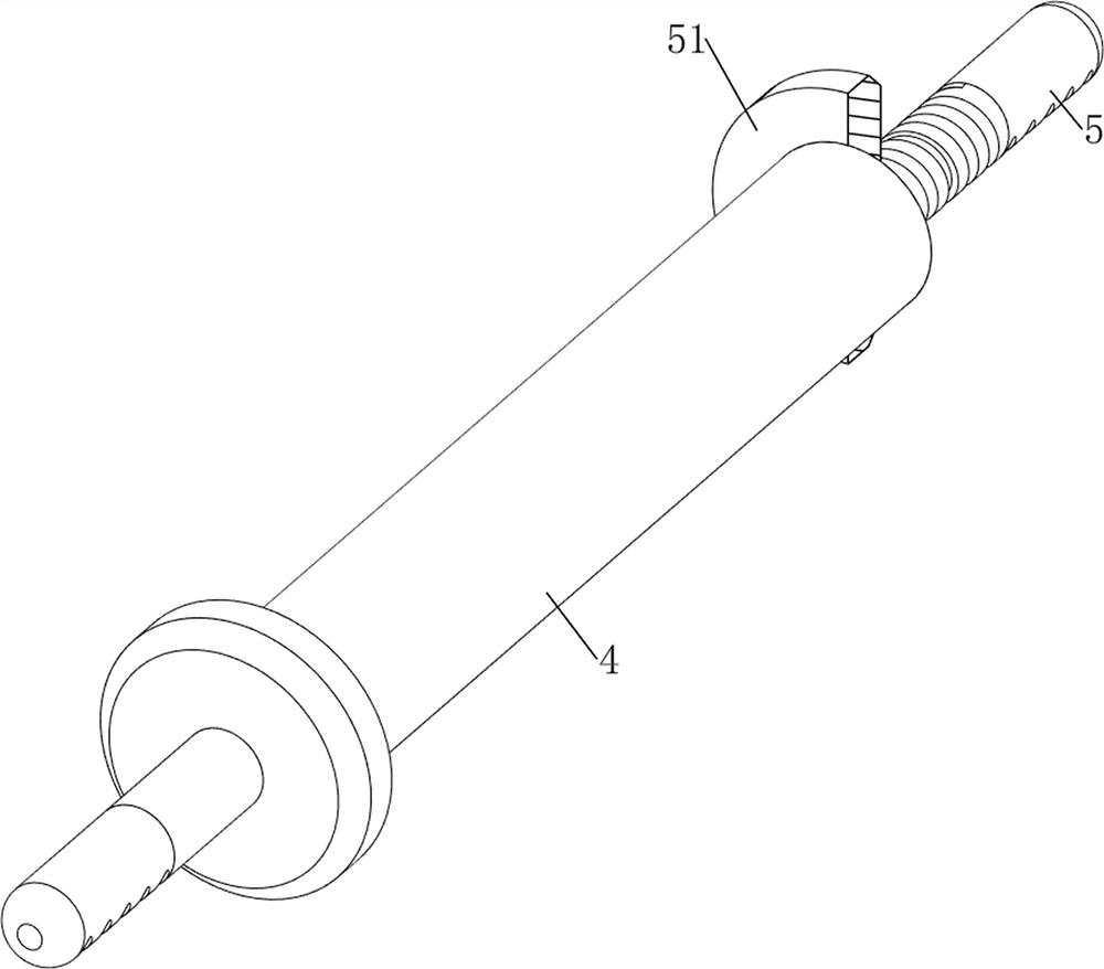
[0092] A kind of gauze rolling equipment for weaving, such as Figure 1-Figure 6 As shown, it includes a base plate 1, a first fixed plate 2, a first support plate 3, a roller 4, a handle 5, a baffle plate 51, a guide shaft 52, a power mechanism 6 and a fixing mechanism 7, and the front and rear sides of the top of the base plate 1 Both are provided with a first fixed plate 2, and the left and right sides of the top of the bottom plate 1 are symmetrically provided with a first support plate 3, the first support plate 3 is located on the left and right sides of the first fixed plate 2 on the same side, and the first support plate on the right side A roller 4 is placed between the tops of the plates 3, and the front and rear sides of the roller 4 are provided with handles 5, the rear side of the roller 4 is threadedly provided with a baffle 51, and the upper part of the first support plate 3 on the left is rotatably provided with a guide A circular shaft 52, a power mechanism 6 ...
Embodiment 2
[0097] On the basis of Example 1, such as figure 1 , Figure 7 , Figure 8 , Figure 9 , Figure 10 and Figure 11 As shown, a cutting mechanism 8 is also included, and the cutting mechanism 8 includes a fourth support plate 81, a first blade 82, a first fixed rod 83, a second spring 84, a fifth support plate 85, a first movable rod 86 and a first movable rod 86. Three springs 87, a fourth support plate 81 is provided on the right side of the top of the first fixed plate 2, a first fixed rod 83 is provided between the fourth support plate 81 tops, and a first fixed rod 83 rear side sliding type is provided with Blade 82, first blade 82 upper left side has groove, is wound with second spring 84 on the first fixed rod 83, and the two ends of second spring 84 are connected with the fourth supporting plate 81 of front side and first blade 82 respectively. Connection, the first fixed plate 2 rear side upper right part of the rear side is provided with the fifth support plate 8...
Embodiment 3
[0101] On the basis of Example 2, such as figure 1 , Figure 12 , Figure 13 , Figure 14 and Figure 15 As shown, a rotating mechanism 10 is also included, and the rotating mechanism 10 includes a seventh support plate 101, a sixth rotating shaft 102, a second transmission assembly 103, a rotating rod 104, a second movable rod 105, a third movable rod 106, a fourth Spring 107, the seventh rotating shaft 108 and roller 109, the middle side of the top of the first fixed plate 2 is provided with the seventh support plate 101, and the bottom of the seventh support plate 101 is all rotatably provided with the sixth rotating shaft 102, the sixth rotating shaft on the front side Between the front side of 102 and the front side of the third rotating shaft 92, a second transmission assembly 103 is arranged. The second transmission assembly 103 is composed of two pulleys and a belt. The front side of the sixth rotating shaft 102 on the front side and the front side of the third rota...
PUM
 Abstract
Description
Claims
Application Information
 - R&D Engineer
- R&D Manager
- IP Professional
- Industry Leading Data Capabilities
- Powerful AI technology
- Patent DNA Extraction
Browse by: Latest US Patents, China's latest patents, Technical Efficacy Thesaurus, Application Domain, Technology Topic, Popular Technical Reports.
© 2024 PatSnap. All rights reserved.Legal|Privacy policy|Modern Slavery Act Transparency Statement|Sitemap|About US| Contact US: help@patsnap.com