Mechanical arm horizontal rotating joint capable of vertically passing through steel wire rope

A technology of horizontal rotation and wire rope, applied in the field of joints, can solve problems affecting motion stability and increasing control difficulty, and achieve the effect of reducing motion inertia, reducing control difficulty, and improving flexibility

Inactive Publication Date: 2021-12-14
TAIZHOU UNIV
View PDF0 Cites 0 Cited by
  • Summary
  • Abstract
  • Description
  • Claims
  • Application Information

AI Technical Summary

Problems solved by technology

In the design of steel wire drive, it is often necessary for the steel wire to pass through a single-degree-of-freedom or multi-degree-of-freedom joint to ensure that its length remains unchanged. The existing design is generally achieved by dynamic compensation of the motor, or by designing the steel wire to pass through the joint axis horizontally. Yes, the former of these two methods will affect the motion stability and increase the difficulty of control, while the latter cannot realize the transmission condition that requires the steel wire rope to pass vertically

Method used


Image

  • Mechanical arm horizontal rotating joint capable of vertically passing through steel wire rope
  • Mechanical arm horizontal rotating joint capable of vertically passing through steel wire rope
  • Mechanical arm horizontal rotating joint capable of vertically passing through steel wire rope

Examples


Embodiment Construction

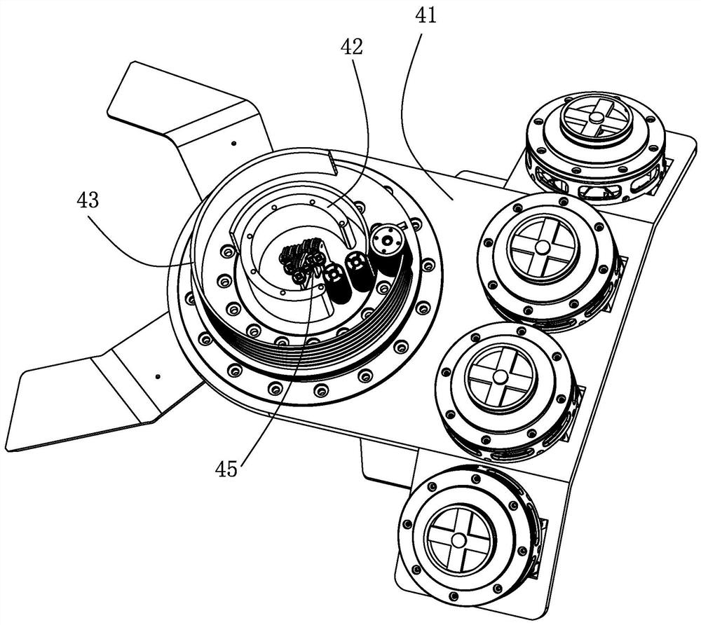
[0020] Such as Figure 1-Figure 4 , Image 6 with Figure 8 As shown, a mechanical arm horizontally rotating joint that can vertically pass through a wire rope is characterized in that it includes a base 41, a flange 42, a support plate 43, a differential transmission mechanism 44, and a wire rope reversing wheel train 45;

[0021] The flange 42 is provided with an axially extending receiving piece 421, the receiving piece 421 is provided with a transition groove group 4211, and the support plate 43 is provided with an axially extending open ring plate 431, and the support plate 43 is provided with a circumferential opening. There is a pair of driving grooves 430, and the opening annular plate 431 is provided with a cloth rope groove group 4311 along the circumferential direction;

[0022] The wire rope reversing wheel train 45 is arranged on the flange plate 42 and the support plate 43, and is used to guide the direction-changing wire rope group 46 in the vertical direction...


PUM


Abstract

A mechanical arm horizontal rotating joint capable of vertically passing through a steel wire rope comprises a base, a flange plate, a supporting disc, a differential transmission mechanism and a steel wire rope reversing wheel train. A bearing piece extending in the axial direction is arranged on the flange plate, and an open annular plate extending in the axial direction is arranged on the supporting disc. The steel wire rope reversing wheel train is arranged on the flange plate and the supporting disc and used for guiding a direction-changing steel wire rope set in the vertical direction to the horizontal direction, the flange plate is connected with the output end of the differential transmission mechanism, the supporting disc is connected with the input end of the differential transmission mechanism, and the differential transmission mechanism is movably installed on the base. A power steel wire rope group for driving the flange plate to rotate is reversely wound in a pair of driving grooves. The length of the steel wire rope of the turning steel wire rope group which achieves horizontal entering and vertical exiting is not changed, the horizontal joint and the vertical joint do not interfere with each other in the movement process, the overall flexibility is improved, and the movement inertia is reduced.

Description

technical field [0001] The invention relates to a joint, in particular to a horizontally rotating joint of a mechanical arm that can vertically pass through a wire rope. Background technique [0002] With the continuous development of industrial technology and the popularization of automation technology, robots have become a necessary means to improve the efficiency of industrial production. The wire drive method can realize the remote control of the motor, which makes the design of the low-inertia joint and parallel drive of the robot more convenient to realize, and improves the precision and flexibility of the robot. In the design of steel wire drive, it is often necessary for the steel wire to pass through a single-degree-of-freedom or multi-degree-of-freedom joint to ensure that its length remains unchanged. The existing design is generally achieved by dynamic compensation of the motor, or by designing the steel wire to pass through the joint axis horizontally. Yes, the...

Claims


Application Information

Patent Timeline
Patent Type & Authority Applications(China)
IPC IPC(8): B25J17/02B25J9/12
CPCB25J17/0258B25J9/104B25J9/126
Inventor 张郑宇张国安付晨东张钦栋
Owner TAIZHOU UNIV
Why Eureka
Try Eureka