Optical chromatography microscopic imaging system and method for rapidly and continuously rotating sample

A technology of microscopic imaging and optical tomography, applied in optics, microscopes, optical components, etc., can solve the problems of limiting imaging time resolution, deformation of biological samples, etc., to avoid mechanical disturbance, improve axial resolution, and achieve various isotropic effect

Active Publication Date: 2021-12-10
北京大学长三角光电科学研究院
View PDF4 Cites 3 Cited by
  • Summary
  • Abstract
  • Description
  • Claims
  • Application Information

AI Technical Summary

Problems solved by technology

However, the existing rotating sample technology is usually realized by mechanical means, and it also has some inherent defects: (1) the speed of mechanical rotation limits the time resolution of imaging; (2) the capillary microtube as the mechanical rotating arm The reflection needs additional correction of numerical aperture; (3) The means on the mechanical rotation sample will cause deformation on the biological sample due to the contact with the sample
While this rotation on the sample is usually mechanical contact, there are the same disadvantages and effects in optical diffraction tomography

Method used


Image

  • Optical chromatography microscopic imaging system and method for rapidly and continuously rotating sample
  • Optical chromatography microscopic imaging system and method for rapidly and continuously rotating sample
  • Optical chromatography microscopic imaging system and method for rapidly and continuously rotating sample

Examples


Embodiment 1

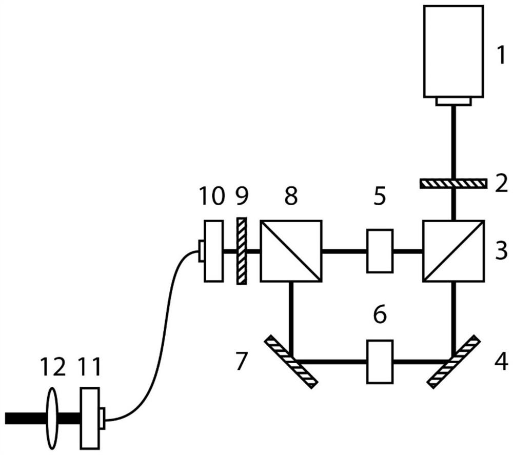
[0081] This embodiment uses optical projection tomography imaging optical paths, such as Figure 4 As shown, the optical layer of the rapid continuous rotary sample of the present embodiment includes: a light-generating optical path, optical projection tomography, image optical path, and synchronous control system;

[0082] The optical projection chromatographic optical path includes a projection illumination laser light source 18, a first acoustic modulator 19, a second telescope system 17, a detecting objective 15, a two-way mirror 14, a first sleeve lens 20, and a first camera 21; projection The lighting laser light source emits a projection illumination laser as a light source of the optical projection tomography, and the first acoustic modulator is quickly modulated with the strength of the primary light. The second telescope system is adjusted to the waist size and the sample matching. When the light is scattered on the sample 16, the transmitted light is collected by the sig...

Embodiment 2

[0085] In this embodiment, an optical diffractive layer is used as a light path, such as Figure 5 As shown, the optical layer of the rapid continuous rotating sample of the present embodiment includes: a light path, optical diffractive tomography, optical path, and synchronous control system;

[0086] The optical diffractive chromatographic optical path includes a diffraction illumination laser light source 22, a second acoustic optical modulator 23, a second 1 / 2 wave plate 24, a third spectroscope 26, a second fiber coupler 26, a third fiber coupler 30, The second optical fiber adapter 27, the third optical fiber adapter 31, the second ratio direct lens 28, the third quadromone 32, the third telescope system 29, detecting objective mirror 15, two-chromaticia 14, fourth split prism 33, the second sleeve lens 34 and the second camera 35; diffraction illumination laser light source emits a diffraction illumination laser light as a light source of optical diffractive chromatography i...


PUM


Abstract

The invention discloses an optical chromatography microscopic imaging system and an optical chromatography microscopic imaging method for rapidly and continuously rotating a sample. Optical tweezers manufactured by linear polarization are used for capturing and rotating a sample, a single-beam gradient force trap is generated, microparticles or cells can be restrained near a focus in a three-dimensional space, anisotropic polarization in the sample is caused at the same time, and therefore a moment depending on an included angle between a birefringence polarization direction and an electric field direction is generated, the captured object can be controlled to synchronously rotate with the polarization direction of the light field. An optical heterodyne interference method is adopted to synthesize a polarized high-speed rotating linear polarized light field for generating optical tweezers, a target sample can be rapidly and continuously rotated in a non-contact mode, mechanical disturbance introduced by a scanning galvanometer is avoided, and especially for optical diffraction tomography, the axial resolution can be improved, and isotropy of the resolution can be achieved. The optical path is compact, and the miniature optical path can be realized.

Description

Technical field [0001] The present invention relates to optical imaging microscopy, particularly relates to optical tomographic imaging microscopic imaging system and a method of rotating the sample in rapid succession. Background technique [0002] Using an optical microscope interaction of light and matter to achieve fine objects to the human eye can not distinguish, for example, cells, and amplifying a technical means for imaging. Compared to other imaging modalities such as electron microscopy microscope, an optical microscope can be achieved noninvasive living cells in real time imaging and observation, it has a wide range for biomedical application scenarios. [0003] The optical tomographic imaging microscopy using light scattered by the sample, or the excitation of the fluorescence signal transmission to perform tomographic imaging of the sample, thereby reconstructing a three-dimensional digital model of imaging on the sample. Wherein the optical projection tomography (O...

Claims


Application Information

Patent Timeline
Patent Type & Authority Applications(China)
IPC IPC(8): G02B21/00G02B21/02G02B21/36
CPCG02B21/00G02B21/02G02B21/36
Inventor 马睿施可彬高翔杨燕青李艳莉贺心雨杨宏龚旗煌
Owner 北京大学长三角光电科学研究院
Why Eureka
Try Eureka