
Optical system for debugging hyperspectral imaging subsystem instead of coaxial three-reflector system

A hyperspectral imaging, coaxial three-mirror technology, applied in optics, optical components, instruments, etc., can solve the problems of long development cycle of hyperspectral imaging system, large aperture of front objective lens, long processing cycle, etc., to improve installation and adjustment The effect of testing ability, reducing the difficulty of installation and adjustment, and high space utilization

Active Publication Date: 2021-12-10
XI'AN INST OF OPTICS & FINE MECHANICS - CHINESE ACAD OF SCI
View PDF11 Cites 0 Cited by
  • Summary
  • Abstract
  • Description
  • Claims
  • Application Information

AI Technical Summary

Problems solved by technology

It is precisely because of the large aperture of the front objective lens that it is bulky, expensive, and has a long processing cycle, resulting in a long development cycle for the hyperspectral imaging system.

Method used


Image

  • Optical system for debugging hyperspectral imaging subsystem instead of coaxial three-reflector system
  • Optical system for debugging hyperspectral imaging subsystem instead of coaxial three-reflector system
  • Optical system for debugging hyperspectral imaging subsystem instead of coaxial three-reflector system

Examples


Embodiment Construction

[0040] The present invention is further explained below in conjunction with the accompanying drawings and embodiments.

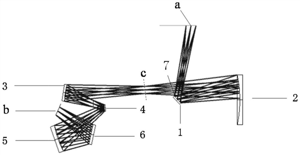
[0041] An alternative anti triax system hyperspectral imaging optical subsystem debug system (hereinafter referred to as an optical system for debugging), comprising a object plane and the image plane B, and the aperture 7 along the optical path between the two successively disposed, a focusing mirror, a first spherical reflector 2, a second spherical mirror 3, a third spherical mirror 4, the fourth spherical mirror 5 and the planar mirror 6; a first focusing lens and a spherical mirror consistent with the structure parameters of a spherical reflector 2 before the original anti triax system focusing mirror and the focusing mirror, spherical mirror 3 and the second, third spherical mirror 4, and the fourth spherical mirror 5 a plane mirror 6, form a folded three off-axis system, instead of the original anti-anti triax remaining lens system; wherein a stop is loca...


PUM


Abstract

The invention relates to an optical system for debugging a hyperspectral imaging subsystem instead of a coaxial three-reflector system, which aims to solve the technical problem that an optical system capable of replacing a front objective lens and testing subsequent subsystems of a hyperspectral imaging system does not exist in the prior art before an on-orbit test. The system comprises an object plane a and an image plane b, and a diaphragm, a focusing lens, a first spherical reflector, a second spherical reflector, a third spherical reflector, a fourth spherical reflector and a plane reflector which are sequentially arranged between the object plane a and the image plane b along a light path, the focusing lens and the first spherical reflector are consistent with the focusing lens and the previous spherical reflector of the original coaxial three-mirror system in structure and parameter; the second spherical reflector, the third spherical reflector and the fourth spherical reflector have the same focal power symbol, and form a folding off-axis three-reflector system with the plane reflector to replace other lenses in the original coaxial three-reflector system; the object plane a is located at the image plane of the original coaxial three-reflector system, and the image plane b simulates an infinite object as an imaging object plane.

Description

Technical field [0001] The present invention relates to an optical system debugging, particularly relates to an alternative anti triax system hyperspectral imaging optical subsystem debug system. Background technique [0002] With the increasing space required for remote sensing applications, the requirements on the width of the hyperspectral imaging system, spatial resolution and other indicators of relative aperture increasing. But the field of view coverage, relatively large pore size and other factors, has led to the increasing volume of the imaging system, in particular increasing front lens diameter, which transfer to the processing means, makes it difficult to verify the test, leading to debug cycle too long. [0003] At present, the sun-synchronous orbit satellites equipped with front lens anti mostly triax system (ie, leading the objective of a particular structure), foreign in-orbit famous front objective lens, such as the US Hubble Space Telescope, its caliber 2.4 mete...

Claims


Application Information

Patent Timeline
Patent Type & Authority Applications(China)
IPC IPC(8): G02B17/06
CPCG02B17/0647G02B17/0663
Inventor 李立波杨莹李西杰王爽邹纯博张智南
Owner XI'AN INST OF OPTICS & FINE MECHANICS - CHINESE ACAD OF SCI
Learn More