Full-tempered vacuum glass and preparation method thereof

A vacuum glass and tempering technology, applied in glass manufacturing equipment, glass tempering, manufacturing tools, etc., can solve problems such as hidden air leakage and reduced sealing strength

Pending Publication Date: 2021-12-10
四川英诺维新材料科技有限公司
View PDF6 Cites 1 Cited by
  • Summary
  • Abstract
  • Description
  • Claims
  • Application Information

AI Technical Summary

Problems solved by technology

[0004] The present invention intends to provide a fully tempered vacuum glass and its preparation method to solve the problem of the decrease in sealing strength and the existence of vacuum in the sealing area caused by hole making and vacuuming in the sealing area in order to eliminate gas residues after the vacuum glass is sealed. The problem of air leakage hazards

Method used


Image

  • Full-tempered vacuum glass and preparation method thereof
  • Full-tempered vacuum glass and preparation method thereof
  • Full-tempered vacuum glass and preparation method thereof

Examples


Embodiment 1

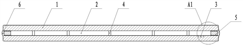
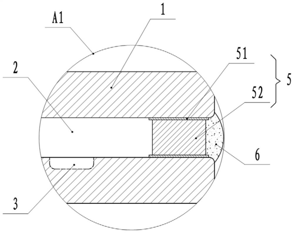
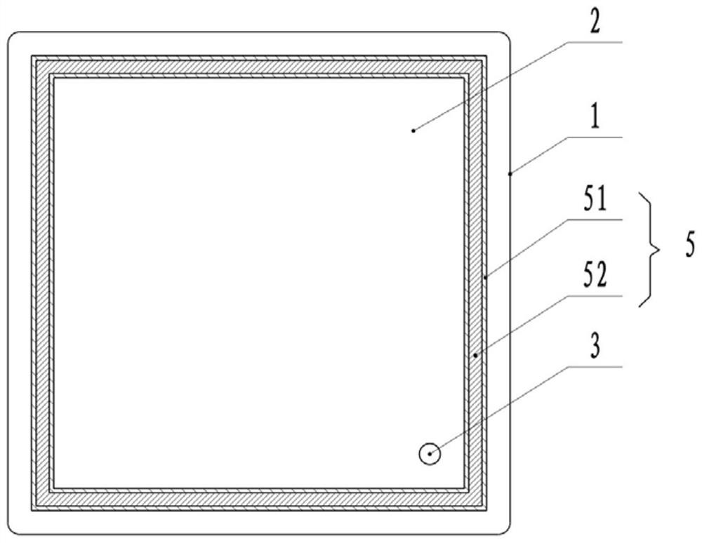
[0049] This embodiment is basically as Figure 1-3 As shown, a fully tempered vacuum glass includes two glass plates 1, a sealing structure is arranged between the two glass plates 1, and a vacuum chamber 2 is formed between the glass plates 1 and the sealing structure.

[0050] A blind hole 3 is arranged on the inner side of one of the glass plates 1, and the blind hole 3 is arranged on the two sides of the glass plate 1 at an equidistant distance of 15-25mm in the region. The diameter of the blind hole 3 is 12mm, and the depth of the blind hole 3 It is 30% of the thickness of the glass plate 1, and a getter (not shown in the figure) is placed in the blind hole 3 . A plurality of support columns 4 are arranged in the vacuum chamber 2 , the distance between adjacent support columns 4 is 50 mm, and the two ends of the support columns 4 are offset against two glass plates 1 respectively.

[0051] The sealing structure is arranged around the two glass plates 1 near the edge area...

Embodiment 2

[0065] The difference between this embodiment and Embodiment 1 is that in this embodiment, the coating and curing of the metal paste and the coating and curing of the solder paste are carried out on the corresponding surfaces of the glass plates A / B, using two different A slurry of ingredients is made. Thus, the process of distributing solid solder strips on the alloy paste coating area is subtracted.

[0066] Coat the metal paste once in the peripheral area around the glass plate A and glass plate B, and then coat a layer of solder paste in the coating area of ​​the metal paste. The coating width of the solder paste is 8mm, and the solder The coating area of ​​the paste had a glass edge of 3 mm, and the coating thickness of the solder paste was 0.5 mm. After the solder paste coating is completed, it is cured by infrared heating. The remaining steps are the same as in Embodiment 1.

Embodiment 3

[0068] The difference between this embodiment and the first embodiment is that in this embodiment, the sintering temperature is 670°C.


PUM

PropertyMeasurementUnit
diameteraaaaaaaaaa
thicknessaaaaaaaaaa
surface stressaaaaaaaaaa

Abstract

The invention relates to the field of vacuum glass, and discloses full-tempered vacuum glass which comprises two glass plates, a sealing structure is arranged between the two glass plates, a vacuum cavity is defined by the glass plates and the sealing structure, blind holes are formed in the inner side faces of the glass plates, and the tempering stress value of the full-tempered vacuum glass is larger than or equal to 90 MPa. The preparation method of the full-tempered vacuum glass comprises the following steps: S1, pretreating a glass plate: processing a blind hole, and coating and curing metal slurry; S2, performing physical tempering: sintering the glass plate and the metal slurry in an integral heating manner; S3, laying a support and a solder; S4, placing a getter in the blind hole; S5, performing laminating and sealing: feeding the two glass plates into a vacuum cavity for laminating, and then carrying out plasma bombardment treatment; and S6, after secondary sealing, activating the getter to obtain the full-tempered vacuum glass. According to the invention, the problems that the sealing strength is reduced and the hidden danger of air leakage exists due to the fact that an air exhaust hole is reserved in the vacuum glass or hole making and vacuumizing are carried out in a sealing area after sealing are solved.

Description

technical field [0001] The invention relates to the field of vacuum glass, in particular to a fully tempered vacuum glass and a preparation method thereof. Background technique [0002] Vacuum glass is a glass that seals the surroundings of two pieces of flat glass and evacuates the gap between them. Vacuum glass is a new type of glass deep-processing product, and it is also a transparent and energy-saving green building material. It combines the technical advantages of coated glass and insulating glass. Excellent performance. [0003] At present, the processing process of vacuum glass is usually to coat two or more glass plates (tempered glass) with a metal paste layer around them, and then sinter them in the form of local heating, and then weld them together after sintering. After assembling, a vacuum layer of 0.3mm to 0.4mm will be formed between the two glass plates. Metal supports are arranged in an array between the two glass plates to offset the atmospheric pressure...

Claims


Application Information

Patent Timeline
Patent Type & Authority Applications(China)
IPC IPC(8): C03C27/08C03C17/10C03B27/012C03C23/00
CPCC03C27/08C03C17/10C03B27/012C03C23/006
Inventor 蔡邦辉刘勇江龚有来王国焦鲜华
Owner 四川英诺维新材料科技有限公司
Why Eureka
Try Eureka