Low-stress optical cable pay-off device

A pay-off device and low-stress technology, which is applied in the field of low-stress optical cable pay-off devices, can solve problems such as pay-off operations and difficult winding reels, and achieve the effects of easy installation, reduced labor intensity, and improved convenience

Inactive Publication Date: 2021-12-10
深圳市达富实业有限公司
View PDF0 Cites 0 Cited by
  • Summary
  • Abstract
  • Description
  • Claims
  • Application Information

AI Technical Summary

Problems solved by technology

[0003] In view of the above-mentioned related technologies, the inventor believes that there are the following defects: in the process of paying out the low-stress optical cable, it is necessary to use the pay-off equipment, and the construction personnel will wind the low-stress optical cable The reel is erected in the pay-off device. At this time, the low-stress optical cable is set off the ground. When installing, the construction personnel will continuously pull one end of the low-stress optical cable to lay the low-stress optical cable to the foundation pit or the interior of the underground pipeline; In the process of laying the low-stress optical cable, due to the different specifications such as the wire diameter of the low-stress optical cable, the sizes of the winding reels of the various components shipped from the factory are different at this time. The structure of the wire device is fixed, so it is difficult to pay off wire reels of various sizes and specifications, so there is room for improvement

Method used


Image

  • Low-stress optical cable pay-off device
  • Low-stress optical cable pay-off device
  • Low-stress optical cable pay-off device

Examples


Embodiment Construction

[0032] The following is attached Figure 1-3 The application is described in further detail.

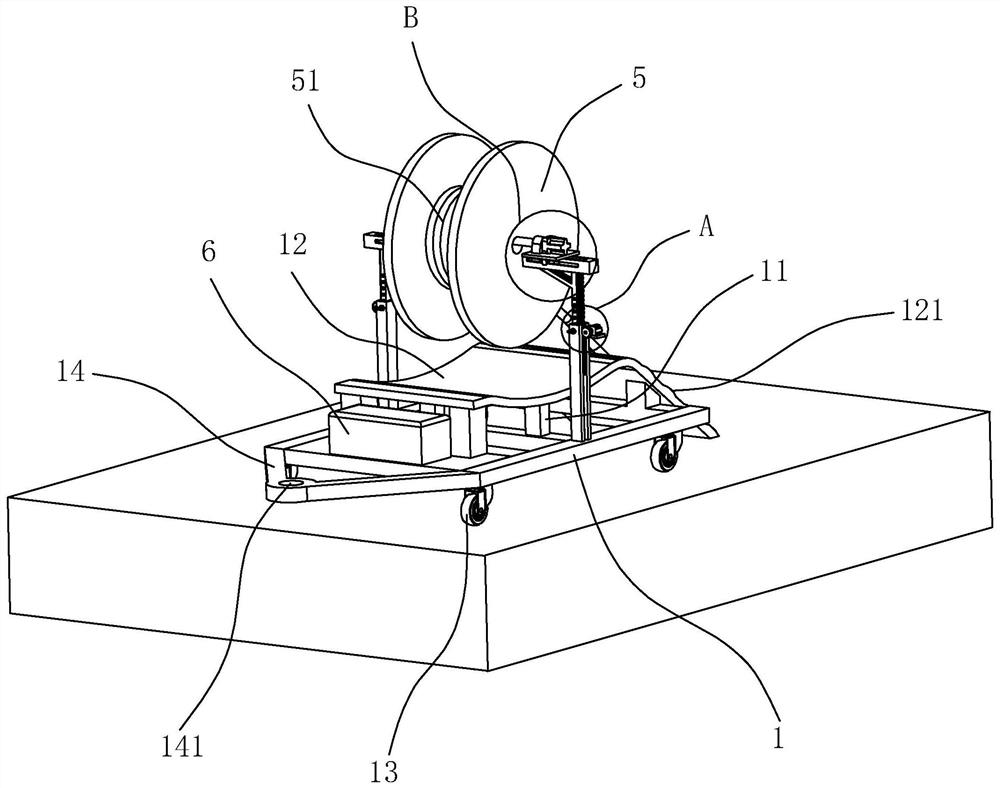
[0033] The embodiment of the present application discloses a low-stress optical cable pay-off device. refer tofigure 1 , the ground is set horizontally, and the low-stress optical cable 51 needs to be laid. During the laying process of the low-stress optical cable 51, the low-stress optical cable 51 is wound up on the reel 5, and before the laying of the low-stress optical cable 51, the strands of the reel 5 are transported to the construction site.

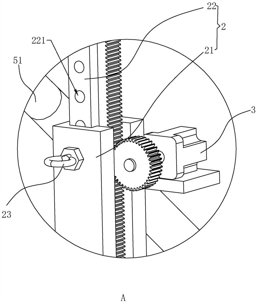
[0034] refer to figure 1 and figure 2 , this kind of low-stress optical cable pay-off device includes a base 1 and two sets of support rods 2, the base 1 is formed by welding several groups of square steel pipes, the base 1 is set horizontally, and the four corners of the lower end surface of the base 1 are all Rotation is connected with universal wheel 13. The front end of the base 1 is integrally fixed with a hanger 14, the plan...


PUM


Abstract

The invention relates to a low-stress optical cable pay-off device. The low-stress optical cable pay-off device comprises a base and two sets of supporting rods; the two sets of supporting rods are vertically fixed to the edges of the two sides of the base correspondingly; each supporting rod comprises a main rod body and an auxiliary rod body, wherein the lower end of the main rod body is fixedly connected with the base, the main rod body is of a box iron structure, and a first motor is fixed to the upper end of each main rod body; the auxiliary rod bodies are in inserted connection with groove openings of the main rod bodies in a sliding manner, the end faces of the sides, deviating from the groove bottoms of the main rod bodies, of the auxiliary rod bodies are of rack structures, the first motors drive the auxiliary rod bodies to slide up and down along the groove openings of the main rod bodies, the auxiliary rod bodies are provided with a plurality of sets of inserting holes distributed at equal intervals in the vertical direction, and positioning bolts penetrating the auxiliary rod bodies are inserted and connected to the upper ends of the main rod bodies; and clamping assemblies which are horizontally and oppositely arranged are fixed to the upper ends of the two sets of auxiliary rod bodies, and a winding wheel wound with a low-stress optical cable is clamped between the two sets of clamping assemblies. The base is provided with a battery used for supplying power to the first motors. According to the low-stress optical cable pay-off device, winding wheels different in size can be installed, and convenience of the installing process is improved.

Description

technical field [0001] The present application relates to the field of low-stress optical cable pay-off devices, in particular to a low-stress optical cable pay-off device. Background technique [0002] Low-stress optical cable is manufactured to meet optical, mechanical or environmental performance specifications. It is a communication cable assembly that uses one or more optical fibers placed in a sheath as a transmission medium and can be used individually or in groups. . The basic structure of low-stress optical cable is generally composed of several parts such as cable core, reinforced steel wire, filler and sheath. In addition, there are waterproof layers, buffer layers, insulated metal wires and other components according to needs. [0003] In view of the above-mentioned related technologies, the inventor believes that there are the following defects: in the process of paying out the low-stress optical cable, it is necessary to use the pay-off equipment, and the cons...

Claims


Application Information

Patent Timeline
Patent Type & Authority Applications(China)
IPC IPC(8): B65H49/20B65H49/34
CPCB65H49/20B65H49/34
Inventor 刘合一
Owner 深圳市达富实业有限公司
Why Eureka
Try Eureka