Micro permanent magnet motor for liquid cooling pump

A technology for permanent magnet motors and pumps, used in magnetic circuits, electromechanical devices, electrical components, etc., can solve the problems of insufficient structural strength, weak radial impact resistance, unreasonable flow channel settings, etc., to avoid relative rotational motion. , the effect of reducing volume and light weight

Active Publication Date: 2021-12-07
XIAN AEROSPACE PRECISION ELECTROMECHANICAL INST
View PDF4 Cites 0 Cited by
  • Summary
  • Abstract
  • Description
  • Claims
  • Application Information

AI Technical Summary

Problems solved by technology

[0008]The present invention provides a micro permanent magnet motor for liquid-cooled pumps, which solves the unreasonable setting of the flow channels of traditional micro liquid-cooled pump motors, insufficient structural strength and radial Structural design problems with weak impact resistance

Method used


Image

  • Micro permanent magnet motor for liquid cooling pump
  • Micro permanent magnet motor for liquid cooling pump
  • Micro permanent magnet motor for liquid cooling pump

Examples


Embodiment Construction

[0054] The present invention will be further elaborated and described below in conjunction with the accompanying drawings and specific embodiments.

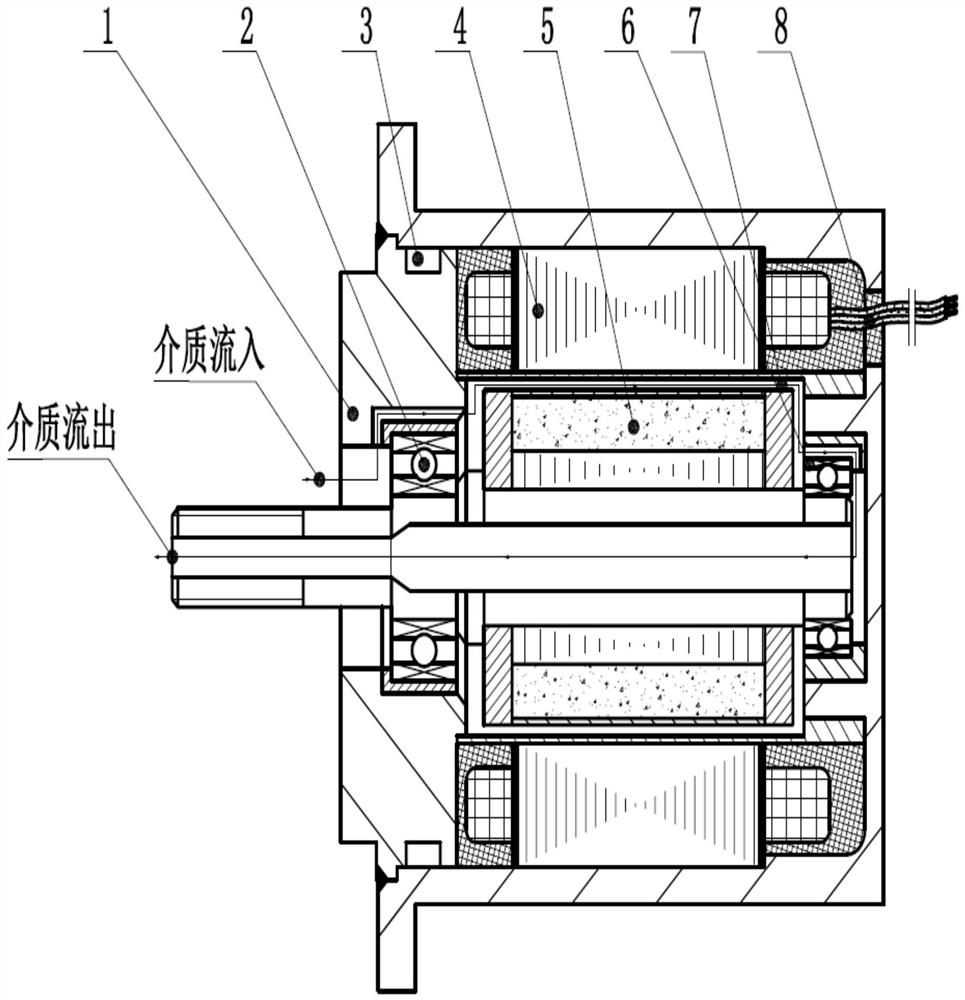
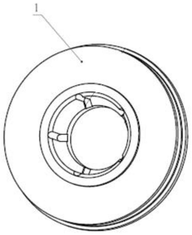
[0055] The present invention relates to a micro permanent magnet motor for a liquid-cooled pump. The outer diameter of the motor is 8 mm, the motor efficiency can reach 95%, and the rated speed of the motor is 16000 r / min. like figure 1As shown: the motor includes an end cover assembly 1, a casing 45, a stator assembly 4 and a rotor assembly 5. After the end cover assembly 1 and the casing 45 are fixed and sealed, a stator and rotor assembly cavity for the stator assembly 4 and the rotor assembly 5 is formed. In the stator-rotor installation cavity, the rotor assembly 5 is connected to the end cover assembly 1 through the front bearing 2, the rotor assembly 5 is connected to the stator assembly 4 through the rear bearing 6, the rear bearing 6 is located at the tail of the casing 8, and the stator assembly 4 is located at the casi...


PUM


Abstract

The invention particularly relates to a micro permanent magnet motor for a liquid cooling pump, and solves the structural design problems of large friction loss, large mechanical gap, low efficiency, insufficient structural strength and weak resistance to radial impact force of a traditional micro liquid cooling pump motor sealing element. The micro permanent magnet motor for the liquid cooling pump comprises an end cover assembly, a casing, a stator assembly and a rotor assembly. The end cover assembly and the casing are fixedly and hermetically connected to form a stator and rotor mounting cavity; the stator assembly is located in the stator and rotor mounting cavity and comprises a stator sheath and a stator armature which are coaxially arranged in sequence from inside to outside; and the rotor assembly comprises a motor shaft, and comprises a rotor core, magnetic steel and a rotor sheath which are positioned in the stator and rotor mounting cavity and are coaxially arranged on the motor shaft in sequence from inside to outside. According to the invention, the first flow channel is arranged on the end cover assembly, the second flow channel is arranged on the rear lining, the third flow channel is arranged in the motor shaft, the three flow channels are matched with the gaps for use, the flow resistance of cooling liquid in the motor is reduced, and the efficiency of the motor is improved.

Description

technical field [0001] The invention belongs to the technical field of motors, and in particular relates to a miniature permanent magnet motor for a liquid-cooled pump. Background technique [0002] With the advancement of aerospace technology, liquid-cooled pump technology has been widely used. As an important part of the liquid-cooled pump system, the permanent magnet motor provides power for the liquid-cooled pump. The structure of the traditional permanent magnet motor adopts a structural design in which the output shaft extends out of the dynamic seal to prevent the coolant from entering the motor. Due to the high requirements of the dynamic seal structure design on the seals and friction pairs, leakage or non-insulation often occurs, affecting the reliability of the motor. Work. [0003] The permanent magnet motor of the existing liquid-cooled pump adopts a structure in which the cooling liquid circulates in the inner cavity of the liquid-immersed motor. The flow res...

Claims


Application Information

Patent Timeline
Patent Type & Authority Applications(China)
IPC IPC(8): H02K5/20H02K5/173H02K9/19H02K7/04H02K5/22H02K5/04H02K1/12H02K1/18
CPCH02K5/203H02K5/1732H02K9/19H02K7/04H02K5/225H02K5/04H02K1/12H02K1/185
Inventor 李吉兴李玉涛曹宽韩凯郭宇帆张丽娟
Owner XIAN AEROSPACE PRECISION ELECTROMECHANICAL INST
Why Eureka
Try Eureka