
Electric hinge

An electric hinge and hinge technology, applied in the field of hinges, can solve the problem that the hinge cannot control the automatic opening and closing of the door, etc., and achieve the effect of facilitating life and improving quality.

Inactive Publication Date: 2021-12-07
XIAMEN QIANYUAN TECH SERVICE CO LTD
View PDF0 Cites 0 Cited by
  • Summary
  • Abstract
  • Description
  • Claims
  • Application Information

AI Technical Summary

Problems solved by technology

[0003] The purpose of the present invention is to provide an electric hinge structure and method to solve the problem that the existing hinge cannot control the automatic opening and closing of the door, and to facilitate the automatic opening and closing of the actual door or window by using remote control technology

Method used


Image

  • Electric hinge
  • Electric hinge
  • Electric hinge

Examples


Embodiment 1

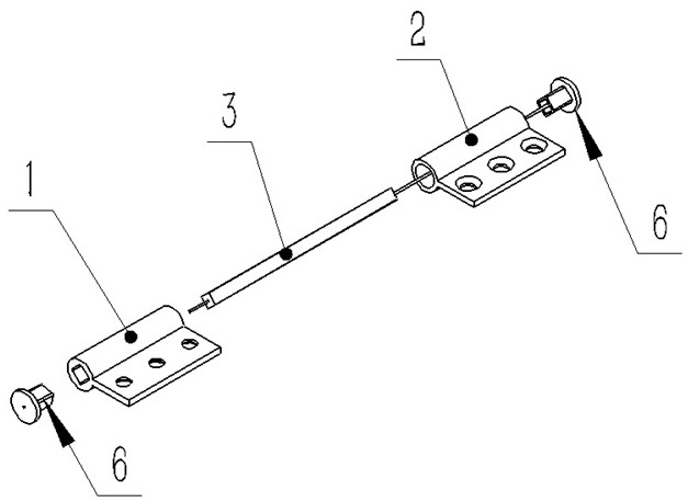
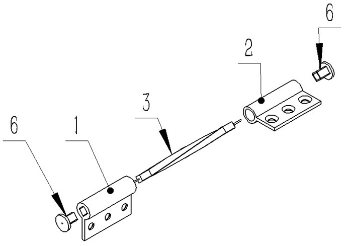
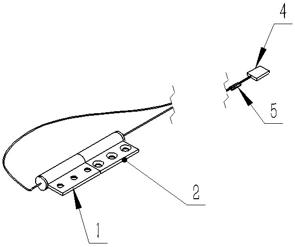
[0025] An electric hinge, including: a. an upper hinge 1, which is fixed on the door frame or window frame; b. a lower hinge 2, which is fixed on the door or window; c. a memory alloy bar 3, One end of it is fixedly connected with the upper hinge 1, and its other end is fixedly connected with the lower hinge 2. When the temperature of the memory alloy strip 3 changes to the phase transition temperature of the memory alloy strip 3, the memory alloy strip 3 It will be deformed according to the preset shape, thereby forcing the upper hinge 1 and the lower hinge 2 to rotate relative to each other, thereby driving the rotation of the door or window; d. a power supply 4, which is used to provide electric energy to force the memory alloy strip 3 The temperature changes; e. a power switch 5, which is used to control the power supply to heat or cool the memory alloy strip.

[0026] Further, one end of the memory alloy strip 3 is connected to the positive pole of the power supply 4, and...

Embodiment 2

[0036] An electric hinge, including: a. an upper hinge 11, which is fixed on the door frame or window frame; b. a lower hinge 12, which is fixed on the door or window; c. a memory alloy bar 13, Its one end is fixedly connected with the upper hinge 11, and its other end is fixedly connected with the lower hinge 12. When the temperature of the memory alloy strip 13 changes to the phase transition temperature of the memory alloy strip 13, the memory alloy strip 13 Will be deformed according to the preset shape, thereby forcing the upper hinge 11 and the lower hinge 12 to rotate relatively, thereby driving the rotation of the door or window; d. a power supply 16, which is used to provide electric energy to force the memory alloy strip 13 The temperature changes; e. a power switch 15, which is used to control the power supply 16 to heat or cool the memory alloy strip 13.

[0037] Further, a heating rod 14 is inserted on the memory alloy bar 13, and the heating rod 14 is connected t...


PUM


Abstract

The invention discloses an electric hinge. The electric hinge comprises an upper hinge, a lower hinge, a memory alloy strip, a power supply and a power switch, wherein the upper hinge is fixed on a door frame or a window frame; the lower hinge is fixed on the door or the window; one end of the memory alloy strip is fixedly connected with the upper hinge, the other end of the memory alloy strip is fixedly connected with the lower hinge, and when the temperature of the memory alloy strip changes to the phase transition temperature of the memory alloy strip, the memory alloy strip deforms according to a preset form, so that the upper hinge and the lower hinge are forced to rotate relatively, and therefore, a door or a window is driven to rotate; the power supply is used for providing electric energy to force the temperature of the memory alloy strip to change; and the power switch is used for controlling the power supply to heat or cool the memory alloy strip. According to the electric hinge, opening and closing of the door or the window can be controlled through remote control, trouble and labor are saved, life of people is greatly facilitated, meanwhile, life quality is improved, and home life is more intelligent.

Description

technical field [0001] The invention relates to a hinge, more specifically, the invention relates to an electric hinge. Background technique [0002] At present, the mechanical hinges on the market are composed of upper and lower hinges and a rotating shaft. The structure is relatively simple and the function is single. It can only realize the function of rotating the door or window around the rotating shaft. Some hydraulic auxiliary hinges are also used to realize the speed control of door closing, and the door needs to be opened and closed manually, so there is no way to realize the automatic opening and closing of doors or windows through hinges. Contents of the invention [0003] The purpose of the present invention is to provide an electric hinge structure and method to solve the problem that the existing hinges cannot control the automatic opening and closing of doors, and to facilitate the automatic opening and closing of doors or windows by using remote control tec...

Claims


Application Information

Patent Timeline
Patent Type & Authority Applications(China)
IPC IPC(8): E05D3/02E05D11/00E05F15/60E05F15/40
CPCE05D3/02E05D11/00E05F15/60E05F15/40
Inventor 卢能才
Owner XIAMEN QIANYUAN TECH SERVICE CO LTD
Learn More