Cloth drying room capable of automatically draining water based on water pressure

A technology for automatic drainage and fabric drying, which is applied in the processing of textile materials, equipment configuration for processing textile materials, textiles and papermaking, etc. Improving drainage and avoiding water backflow in time

Pending Publication Date: 2021-12-03
李群
View PDF6 Cites 0 Cited by
  • Summary
  • Abstract
  • Description
  • Claims
  • Application Information

AI Technical Summary

Problems solved by technology

[0003] At present, in the process of textile processing, in order to ensure the cleanliness of the produced fabrics, it is often necessary to wash the fabrics, and there will be more water on the washed fabrics. In order to make the fabrics dry quickly, it is generally accelerated through the drying room During the drying of the cloth, a certain amount of water will fall during the drying process of the cloth. A water storage chamber is often set up on the floor of the drying room to receive the falling water. However, with the continuous operation of the drying room, the water storage chamber The water in the tank will reach the upper limit of its own capacity. Therefore, every once in a while, it is necessary to manually drain the water storage chamber, and the water storage chamber can continue to receive the falling water, but this will consume a lot of manpower, and sometimes Artificial drainage may cause untimely drainage, which will affect the drainage of the drying room

Method used


Image

  • Cloth drying room capable of automatically draining water based on water pressure
  • Cloth drying room capable of automatically draining water based on water pressure
  • Cloth drying room capable of automatically draining water based on water pressure

Examples


Embodiment Construction

[0027] The following examples are for illustrative purposes only and are not intended to limit the scope of the invention.

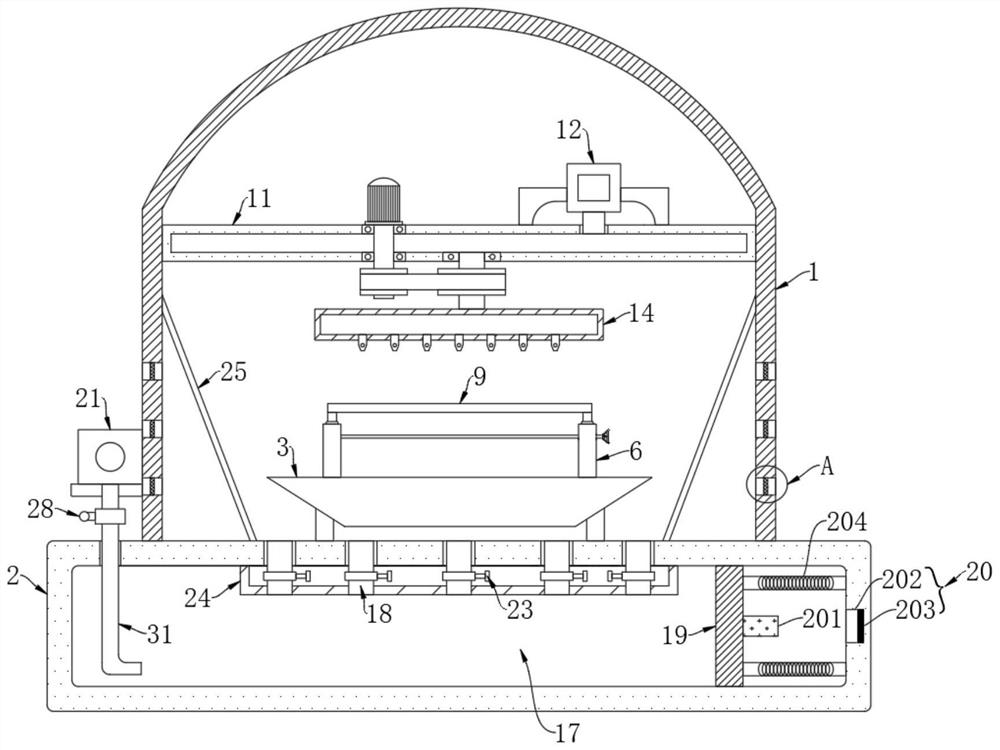
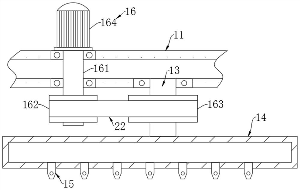
[0028] like Figure 1-5 As shown, a cloth drying room with automatic drainage based on water pressure includes a room body 1, and condensation deflectors 25 are installed on both sides of the room body 1, and the condensation deflectors 25 are made of copper materials. , the room body 1 is provided with a plurality of air holes 26 matched with the condensation deflector 25, and a filter screen 27 is embedded in the air hole 26. The water vapor can be in contact with the condensation guide plate 25, so that the water vapor is converted from a gaseous state to a liquid state, and is discharged through the condensation deflector 25 to the water inlet pipe 18, reducing the possibility of cloth contacting water vapor and improving the drying efficiency of the cloth. The condensation deflector 25 Copper material can be used to improve its own heat dissipation...


PUM


Abstract

The invention belongs to the field of spinning, and particularly relates to a cloth drying room capable of automatically draining water based on water pressure. The cloth drying room comprises a room body; the room body is fixedly connected with the ground; the ground is fixedly connected with a hollow supporting seat; the hollow supporting seat is provided with a water inlet and a water outlet; the hollow supporting seat is fixedly connected with two hollow supporting rods; a threaded sleeve is rotationally connected inside each hollow supporting rod; and a threaded rod is connected inside each threaded sleeve in a threaded mode. Through cooperation of a sliding plate and a reset spring, when water in a water storage cavity reaches a certain volume, the sliding plate can slide and compress the reset spring under the action of water pressure, a conductive block is in butt joint with a conductive sheet, a pressure trigger switch is automatically closed, and then a water pump automatically pumps the water in the water storage cavity, so that the labor loss caused by manual drainage is avoided; and the drainage is timely, so that the drainage performance of the drying room can be effectively improved.

Description

technical field [0001] The invention belongs to the field of textiles, in particular to a cloth drying room capable of automatic drainage based on water pressure. Background technique [0002] The original meaning of textile is taken from the general term of spinning and weaving, but with the continuous development and improvement of the textile knowledge system and subject system, especially after the emergence of non-woven textile materials and three-dimensional composite weaving technologies, it is not only the traditional hand spinning And weaving, also including clothing, industrial and decorative textiles produced by non-woven technology and modern three-dimensional weaving technology. [0003] At present, in the process of textile processing, in order to ensure the cleanliness of the produced fabrics, it is often necessary to wash the fabrics, and there will be more water on the washed fabrics. In order to make the fabrics dry quickly, it is generally accelerated thro...

Claims


Application Information

Patent Timeline
Patent Type & Authority Applications(China)
IPC IPC(8): D06B15/00D06B23/20
CPCD06B15/00D06B23/20
Inventor 李群
Owner 李群
Why Eureka
Try Eureka