
Feeding device for rotary swaging forming

A feeding device and guide rail technology, which is applied in the field of rotary forging feeding devices, can solve problems such as upsetting, and achieve the effect of convenient control and simple structure

Pending Publication Date: 2021-12-03
ANHUI UNIV OF SCI & TECH
View PDF0 Cites 0 Cited by
  • Summary
  • Abstract
  • Description
  • Claims
  • Application Information

AI Technical Summary

Problems solved by technology

The device has a reasonable structure and simple control, which can solve the upsetting problem caused by the reverse flow of the material during the rotary forging forming, improve the tool life, improve the forming quality, and at the same time ensure the axis height and fixation of different diameter bars or pipes. The center of the swaging die is the same

Method used


Image

  • Feeding device for rotary swaging forming
  • Feeding device for rotary swaging forming
  • Feeding device for rotary swaging forming

Examples


Embodiment Construction

[0034] The material introduction device for rotary swaging involved in the present invention will be further described below with reference to the accompanying drawings.

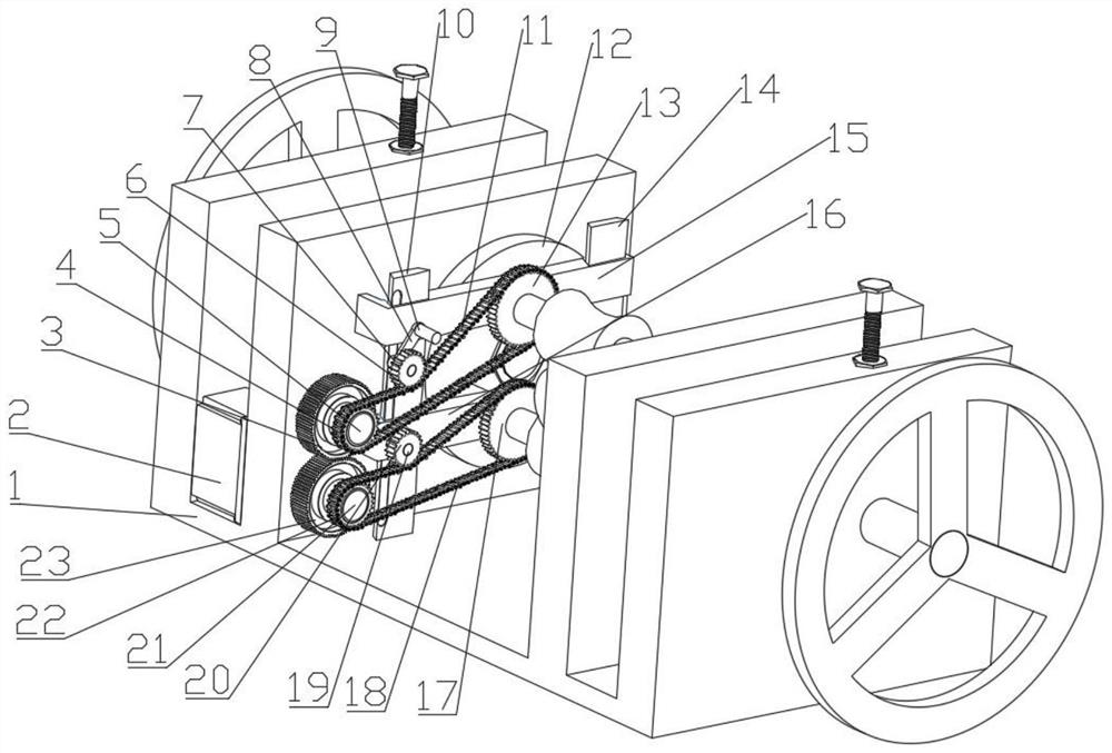
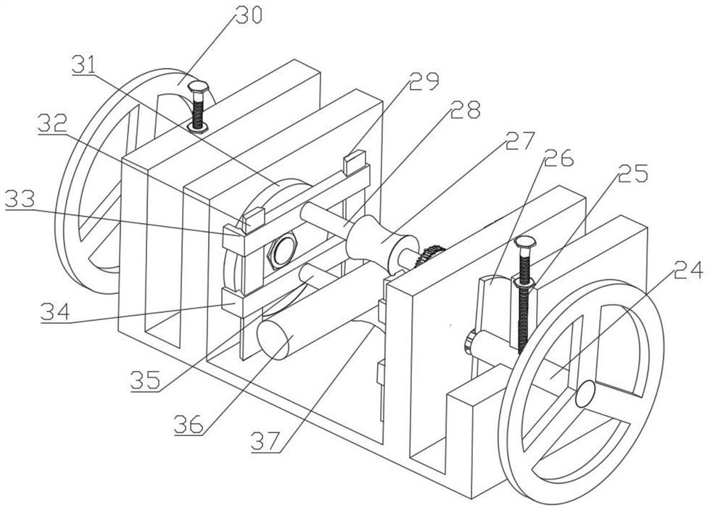
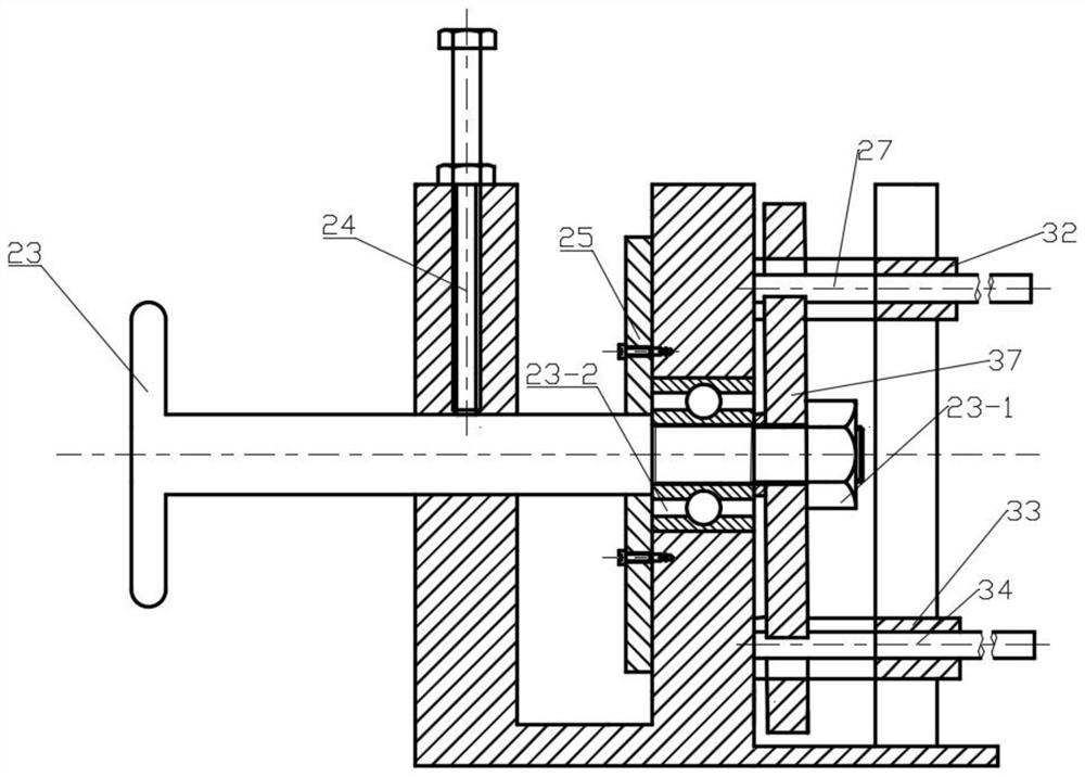
[0035] figure 1 It is a structural schematic diagram of a material introduction device for swaging forming according to the present invention, figure 2It is a schematic view from another perspective of the structure of the swaging feeding device of the present invention. It is mainly composed of a base (1), a motor (2), an adjustment mechanism, a clamping mechanism, a transmission mechanism and a tensioning mechanism. The adjustment mechanism includes guide rails (14, 29, 32), chute guide rails (10), beams (15, 16, 33, 34), slide bars (7, 19), connectors (8), fixed rods (9), Adjust shaft (24, 30), stop screw (25). Among them, the chute guide rail (10) cooperates with the beam (15, 16) through the dovetail groove (15-1); . The tensioning mechanism comprises a slide bar (7, 19), a connecting piece (8), a...


PUM


Abstract

The invention provides a feeding device for rotary swaging forming. The feeding device is mainly composed of a base, a motor, an adjusting mechanism, a clamping mechanism, a transmission mechanism and a tensioning mechanism. The relative position of the clamping mechanism is symmetrically adjusted through the adjusting mechanism, so that the clamping center of the clamping mechanism is not changed; when the adjusting mechanism adjusts the position of the clamping mechanism through the tensioning mechanism, a chain or a belt in the transmission mechanism can still be in a tensioning state; and rotation of the clamping mechanism is achieved through the transmission mechanism, and continuous feeding is achieved through the clamping force of the clamping mechanism. The feeding device for rotary swaging forming provided by the invention is simple in structure and convenient to control, the problem that the reverse flow of materials is larger than the forward flow in the rotary swaging process can be solved, and the axis height of bars or pipes with different diameters can be the same as the center of a rotary swaging die when the bars or the pipes are fed. The feeding device is arranged at the outlet position of a rotary swaging machine, and the material guiding function of the bars or pipes with different diameters can be achieved.

Description

technical field [0001] The invention belongs to the field of mechanical engineering, and in particular relates to a swaging forming feeding device. Background technique [0002] Rotary forging is a progressive forming method that uses high-speed rotation of the forging die and applies high-frequency forging force to blanks such as bars or pipes to reduce the cross-sectional size or change the shape of the blank. It is a metal forming process with discontinuous step-by-step forming and uniform deformation. [0003] Rotary forging can process a large number of different shapes and inner cavities, and has near-net shape, high material utilization rate, continuous fiber streamline, and can increase the strength of parts through work hardening. At present, rotary forging generally uses a mechanical system and a hydraulic system to clamp and feed materials at a constant speed. During the downward process of the forging die, the blank is continuously fed in the axial direction. W...

Claims


Application Information

Patent Timeline
Patent Type & Authority Applications(China)
IPC IPC(8): B65G47/74
CPCB65G47/74
Inventor 刘志卫胡圳威胡海霞张顺利
Owner ANHUI UNIV OF SCI & TECH
Learn More