
Bypass coupling three-wire indirect electric arc welding method with controllable electric arc space structure

A technology of bypass coupling and space structure, applied in arc welding equipment, welding equipment, welding accessories, etc., can solve problems such as unfused side walls, increased welding current, and narrow welding process parameters in narrow gaps

Active Publication Date: 2021-12-03
725TH RES INST OF CHINA SHIPBUILDING INDAL CORP
View PDF12 Cites 1 Cited by
  • Summary
  • Abstract
  • Description
  • Claims
  • Application Information

AI Technical Summary

Problems solved by technology

Therefore, the traditional welding technology has low welding efficiency and large total heat input, which is difficult to meet the needs of today's society
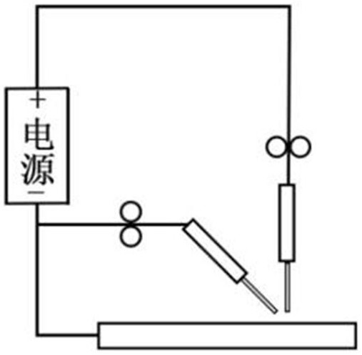
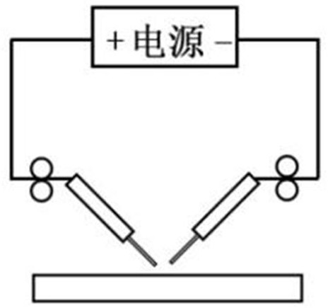
[0003] In order to improve the welding efficiency of traditional welding technology, the following three methods are mainly used: one is to increase the deposition rate (that is, to increase the wire feeding speed), such as T.I.M.E welding, Cable-type wire arc welding, etc., although the welding wire deposition rate has been improved, but due to the increase of welding current, it is easy to cause problems such as the decline of the mechanical properties of the welded joint
The second is to adopt a narrow gap welding process, which reduces the weld metal filling amount by reducing the size of the welding groove. Although the welding efficiency is improved, due to the small groove gap, it is easy to cause "side wall arcing" and the arc stability is poor; at the same time , most of the heat of the arc acts on the bottom of the groove and less heat acts on the side wall of the groove, which is easy to cause unfused defects on the side wall
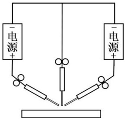
[0005]Patent CN104772552A proposes "a three-wire gas-shielded indirect arc welding method, device, surfacing welding method and narrow gap welding method", the schematic diagram of which is shown in Figure 3, based on the double-wire indirect arc and then introducing An indirect arc not only improves the problem of insufficient heat input of the double-wire indirect arc base metal, but also forms two indirect arcs coupled together, which improves the stability of the arc and increases the adjustable range of welding parameters; in addition, by adjusting The arrangement of the three welding wires expands the width of the arc, changes the distribution of arc energy, and realizes sidewall fusion during narrow gap welding. However, since the three welding wires must contact each other to start the arc, the width of the arc expansion is limited. As a result, the process parameters during narrow gap welding are extremely narrow, and at the same time, the problem of lack of fusion between layers caused by insufficient heat input due to no current passing through the base metal still exists
[0006]Patent CN109079287A proposes "a three-wire gas-shielded indirect arc welding method, device and application", by changing the power connection mode and adopting a mirror-symmetric welding wire row The distribution method optimizes the magnetic field distribution space and obtains a concentrated indirect arc at the same time. Although the energy density of the indirect arc is greatly increased, its width is reduced, which is not conducive to the side wall fusion during narrow gap welding

Method used


Image

  • Bypass coupling three-wire indirect electric arc welding method with controllable electric arc space structure
  • Bypass coupling three-wire indirect electric arc welding method with controllable electric arc space structure
  • Bypass coupling three-wire indirect electric arc welding method with controllable electric arc space structure

Examples


Embodiment 1

[0036] Narrow gap welding is carried out by adopting a bypass coupling three-wire indirect arc welding method with controllable arc space structure described in the present invention. The base material is 300×150×30mm (length×width×height) Q235 steel plate, the welding wire is ER50-6, the diameter of the main wire is 1.6mm, the diameter of the side wire is 1.2mm, and the welding shielding gas is Ar+20%CO 2 And sent out by the main wire welding torch, the air flow rate is 15-20L / min; the weld groove form adopts type I groove, and the groove gap is 10mm. The specific welding process is as follows:

[0037] Step 1, before welding, connect the three welding wires and the base metal 6 to two power sources respectively, wherein the wires on both sides are connected to the negative pole of the bypass power supply 1 at the same time, and the base metal 6 is connected to the negative pole of the main power supply 2 , the main wire 3 is connected to the positive poles of the two power ...


PUM

PropertyMeasurementUnit
diameteraaaaaaaaaa
diameteraaaaaaaaaa
diameteraaaaaaaaaa

Abstract

Provided is a bypass coupling three-wire indirect arc welding method with a controllable arc space structure. Two side wires, a main wire and base metal are connected with two arc welding power sources respectively, the two arc welding power sources are a bypass power source and a main power source respectively, the two side wires are connected with the negative electrode of the bypass power source at the same time, the main wire is connected with the positive electrodes of the two arc welding power sources at the same time, and the base metal is connected with the negative electrode of the main power source. The two side wires and the main wire are arranged in a mirror symmetry mode, the main wire is located in the middle of a groove, and the two side wires are located on the two sides of the main wire respectively and are in mirror symmetry about the vertical plane where the axis of the main wire is located; the relative positions of the ends of the main wire and the two side wires are adjusted, and the ends of the two side wires are located on the same horizontal line; and under the condition that the high welding wire deposition rate is guaranteed, control over base metal heat input and the electric arc energy distribution state is achieved, and finally high-quality and high-efficiency welding of the narrow-gap groove of a medium-thickness plate is achieved.

Description

technical field [0001] The invention relates to the technical field of material processing, in particular to a bypass coupling three-wire indirect arc welding method with controllable arc space structure. Background technique [0002] Medium and thick plates are widely used in industries such as shipbuilding, construction, machinery manufacturing, and pressure vessels, and traditional arc welding techniques such as manual arc welding, semi-automatic melting electrode gas shielded welding, or submerged arc automatic welding are mainly used for welding. Low, high labor intensity, harsh working environment; at the same time, the total heat input of the steel plate is high, and the welding residual stress and welding deformation are large. With the wide application of large structural parts, these problems will become more and more prominent. Therefore, the traditional welding technology has low welding efficiency and large total heat input, which is difficult to meet the needs...

Claims


Application Information

Patent Timeline
Patent Type & Authority Applications(China)
IPC IPC(8): B23K9/095B23K9/12B23K9/16B23K9/32
CPCB23K9/095B23K9/12B23K9/16B23K9/32Y02P70/10
Inventor 胡成辉王杏华吴艳明张金田
Owner 725TH RES INST OF CHINA SHIPBUILDING INDAL CORP
Learn More