Micromechanical acoustic transducer

An acoustic transducer, transducer technology, applied in semiconductor electrostatic transducers, microphones, piezoelectric/electrostrictive transducers, etc.

Pending Publication Date: 2021-11-30
FRAUNHOFER GESELLSCHAFT ZUR FOERDERUNG DER ANGEWANDTEN FORSCHUNG EV
View PDF5 Cites 0 Cited by
  • Summary
  • Abstract
  • Description
  • Claims
  • Application Information

AI Technical Summary

Problems solved by technology

The disclosed disadvantage is that the acoustic transducers are piezoelectric and thus subject to a pre-bending, so that the disclosed measures serve to minimize inaccuracies caused by this pre-bending

Method used


Image

  • Micromechanical acoustic transducer
  • Micromechanical acoustic transducer
  • Micromechanical acoustic transducer

Examples


Embodiment Construction

[0046] Before describing the embodiments of the present invention in detail based on the drawings below, it should be noted that in different drawings, elements, objects and / or structures that are the same and have the same function or action are provided with the same or similar drawings Labels are used so that the descriptions of these elements in different embodiments are interchangeable and / or mutually applicable.

[0047] In the following, according to one embodiment, the bending transducer used comprises a centroid fiber extending in or in the direction of the second axis x. In only certain embodiments, the centroid fibers extend parallel to the second axis. The centroid fiber represents eg the axis of symmetry of the bending transducer or alternatively eg a central electrode arranged between the first electrode and the second electrode.

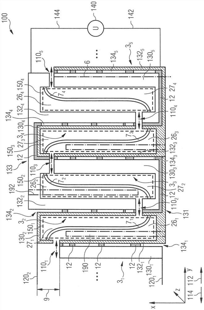
[0048] figure 1 Shows a micromachined acoustic transducer 100 comprising a plurality of curved transducers 3 suspended on one side ...


PUM


Abstract

The invention relates to a micromechanical acoustic transducer comprising a plurality of bending transducers suspended on one side. Each of the plurality of bending transducers is designed for deflection in an oscillation plane and said bending transducers are arranged adjacent to each other in the oscillation plane along a first axis. The plurality of bending transducers extends along a second axis, which is crosswise to the first axis. The bending transducers are suspended on opposite sides in alternation and intermesh with each other. Each bending transducer has a first electrode and a second electrode which are opposite each other along the first axis, in order to cause deflections of the relevant bending transducer along the first axis when voltage is applied. Electrodes of adjacent bending transducers which face each other are electrically connected to each other by a cross-connection which crosses the oscillation plane crosswise to the first axis, such that, for first bending transducers, which are suspended on a first side of the opposite sides, the electrodes which face a first direction along the first axis are electrically connected to each other and to the electrodes, which face a second direction opposite the first direction, of second bending transducers, which are suspended on a second side of the opposite sides, and, for the first bending transducers, the electrodes which face the second direction along the first axis are electrically connected to each other and to the electrodes, facing the first direction, of the second bending transducers.

Description

technical field [0001] Embodiments according to the invention relate to micromechanical sound transducers. Background technique [0002] The technical field of the invention described herein can be outlined by the following three documents describing micromechanical assemblies: [0003] ·WO 2012 / 095185 A1 / Title: MICROMECHANICAL COMPONENT [0004] ·WO 2016 / 202790 A2 / Title: MEMS TRANSDUCER FOR INTERACTING WITH AVOLUME FLOW OF A FLUID AND METHOD FOR PRODUCTING SAME [0005] ·DE 10 2015 206 774 A1 [0006] The above three documents do not provide any indication on how to increase the packing density of the arrangement. Basically, these documents disclose the design of curved transducers and the cavities formed by adjacent curved transducers and their interaction with each other. [0007] Document DE 10 2017 200 725 A1 discloses a layered structure and a method for producing a sensor comprising movable MEMS elements. Below the movable MEMS element, electrode means for detect...

Claims


Application Information

Patent Timeline
IPC IPC(8): H04R1/22H04R17/00H04R19/00B06B1/06
CPCH04R1/227H04R17/00H04R19/005B06B1/0662B06B1/0681H04R2201/003H04R31/00H04R31/006
Inventor 贝尔特·凯泽卢兹·埃里格
Owner FRAUNHOFER GESELLSCHAFT ZUR FOERDERUNG DER ANGEWANDTEN FORSCHUNG EV
Why Eureka
Try Eureka