
Power transmission line galloping dynamic data collection method and device

A technology of dynamic data and transmission lines, applied in measuring devices, vibration testing, testing of machines/structural components, etc., can solve problems such as difficult control of galloping effects, slippage of spacer rods, and inconsistency, etc., to achieve a comprehensive test galloping effect , cost-saving effect

Pending Publication Date: 2021-11-30
GULIFA ELECTRIC
View PDF0 Cites 0 Cited by
  • Summary
  • Abstract
  • Description
  • Claims
  • Application Information

AI Technical Summary

Problems solved by technology

[0002] Due to the eccentric icing of the wires of the transmission line, a low-frequency, large-amplitude self-excited vibration generated under wind excitation is called galloping. This vibration and galloping have no consistency between the phase lines and are extremely It may cause insufficient air gap between conductors, resulting in flashover and tripping, and at the same time, it will cause serious damage to the anti-vibration and anti-galling fittings and devices installed in the gear, resulting in serious consequences such as slipping of spacers, loosening and breaking of anti-vibration hammers, and even causing insulators to fail. , damage to connecting fittings and iron towers
[0003] In the traditional technology, the method of simulating icing by bonding the airfoil resin to the wire, and then using the fan to drive the wire galloping is similar to the actual wire galloping, but the cost is extremely high and the galloping effect is difficult to control. In order to solve the above problem, a method and device for collecting dynamic data of transmission line galloping are now provided

Method used


Image

  • Power transmission line galloping dynamic data collection method and device
  • Power transmission line galloping dynamic data collection method and device
  • Power transmission line galloping dynamic data collection method and device

Examples


Embodiment Construction

[0027] The following will clearly and completely describe the technical solutions in the embodiments of the present invention with reference to the accompanying drawings in the embodiments of the present invention. Obviously, the described embodiments are only some, not all, embodiments of the present invention. Based on the embodiments of the present invention, all other embodiments obtained by persons of ordinary skill in the art without creative efforts fall within the protection scope of the present invention.

[0028] In describing the present invention, it is to be understood that the terms "opening", "upper", "lower", "thickness", "top", "middle", "length", "inner", "surrounding" etc. Indicating orientation or positional relationship is only for the convenience of describing the present invention and simplifying the description, and does not indicate or imply that the components or elements referred to must have a specific orientation, be constructed and operated in a sp...


PUM


Abstract

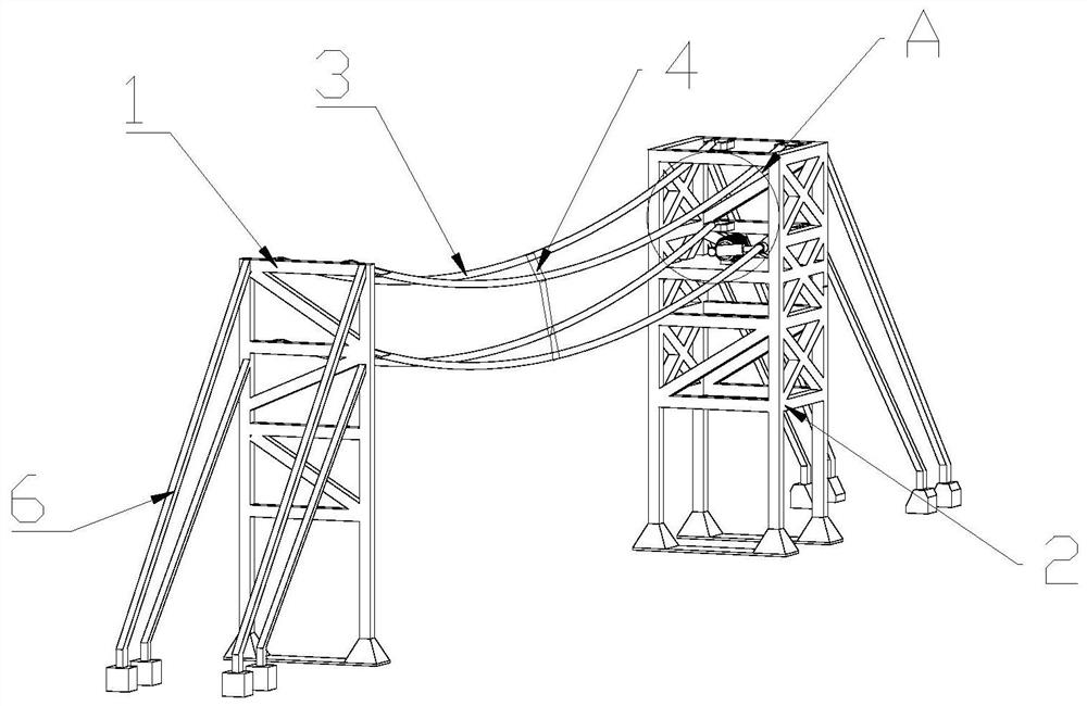
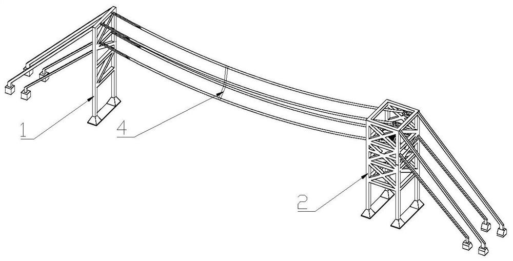
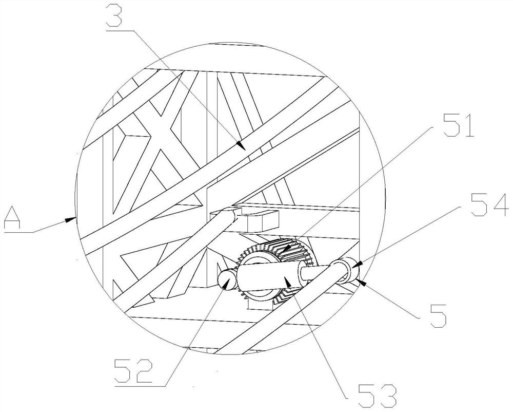
The invention discloses a power transmission line galloping dynamic data collection method and device. The data collection device comprises a fixed tower and a galloping tower, wherein test wires distributed in an array mode are connected between the fixed tower and the galloping tower, a galloping device used for driving the test wires to gallop is fixed to the galloping tower, an anti-galloping device is connected between the test wires, the galloping device is controlled by a computer, and measurement and control software used for controlling the galloping device is installed on the computer. According to the data collection device and method, horizontal swing of the test wires can be achieved by sleeving the fixing sleeves on the test wires located on the lower portion, and vertical swing of the test wires can be achieved by sleeving the fixing sleeves on the test wires located on the upper portion, so that the galloping effect can be tested more comprehensively; and by connecting the phase-to-phase spacers between the test wires, the influence of the phase-to-phase spacers on the galloping effect of the test wires is tested, and the cost is saved.

Description

technical field [0001] The invention relates to a transmission line galloping testing method and device, in particular to a transmission line galloping dynamic data collection method and device. Background technique [0002] Due to the eccentric icing of the wires of the transmission line, a low-frequency, large-amplitude self-excited vibration generated under wind excitation is called galloping. This vibration and galloping have no consistency between the phase lines and are extremely It may cause insufficient air gap between conductors, resulting in flashover and tripping, and at the same time, it will cause serious damage to the anti-vibration and anti-galling fittings and devices installed in the gear, resulting in serious consequences such as slipping of spacers, loosening and breaking of anti-vibration hammers, and even causing insulators to fail. , Damage to connecting fittings and iron towers. [0003] In the traditional technology, the method of simulating icing by...

Claims


Application Information

Patent Timeline
Patent Type & Authority Applications(China)
IPC IPC(8): G01M7/02
CPCG01M7/022G01M7/025
Inventor 陈飞宋玮龚园夏紫晗
Owner GULIFA ELECTRIC
Learn More