
Dust suppression equipment for construction site

A construction site, dust reduction technology, applied in the direction of using liquid separation agent, separation method, dispersed particle separation, etc., can solve the problems of inconvenient operation, low degree of freedom, etc., achieve large spraying range, improve atomization effect, and good dust reduction effect. Effect

Active Publication Date: 2020-12-29
中科长洋(山东)科技有限公司
View PDF4 Cites 0 Cited by
  • Summary
  • Abstract
  • Description
  • Claims
  • Application Information

AI Technical Summary

Problems solved by technology

[0004] The steering operation of the spray barrel of the traditional spray cannon is generally manually operated to adjust the spray angle and spray range, which is inconvenient to operate and the degree of freedom is not high

Method used


Image

  • Dust suppression equipment for construction site
  • Dust suppression equipment for construction site
  • Dust suppression equipment for construction site

Examples


Embodiment 1

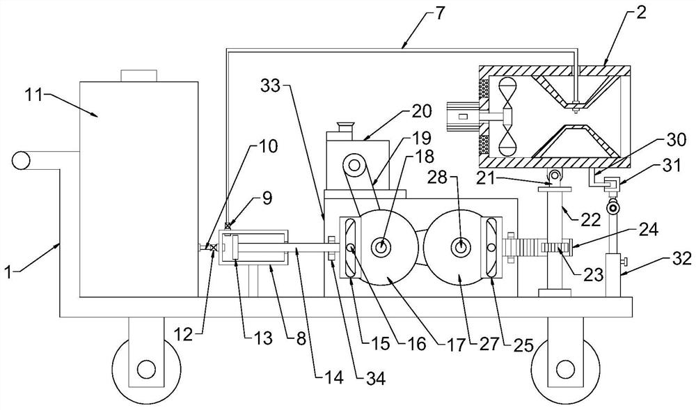
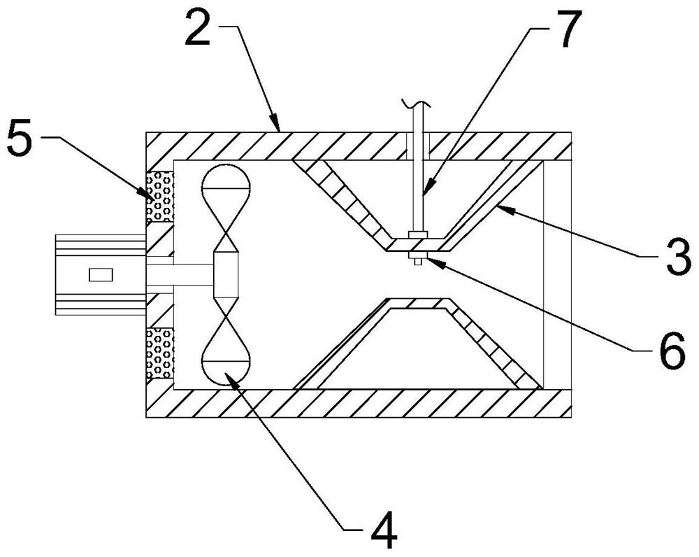
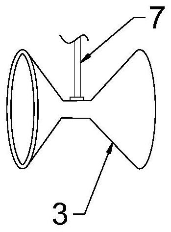
[0023] see Figure 1~2 , in an embodiment of the present invention, a construction site dust suppression equipment, including a car body 1, a spray tube 2, a piston barrel 8 and a diesel engine 20; the car body 1 is provided with rollers for easy movement; A spray tube 2 is provided, and the spray tube 2 is a cylindrical structure with an opening at the right end. A compression cover 3 is arranged inside the spray tube 2. The compression cover 3 is a hollow hourglass-shaped structure with both ends opened. The left side of the compression cover 3 is provided with a fan 4. The fan 4 is fixedly connected to the spray tube 2, the fan 4 is electrically connected to the external power supply, and the middle compression section of the compression cover 3 is provided with a nozzle 6, so that the clear water and the air flow collide at a high speed, and the atomization effect is improved;

[0024] The nozzle 6 is connected to the piston barrel 8 through the water inlet pipe 7, the wat...

Embodiment 2

[0028] see figure 1 with Figure 5 The difference between this embodiment and Embodiment 1 is: the front end of the spray tube 2 is fixedly connected with a guide rod 30, the guide rod 30 is a columnar rod, the guide rod 30 is nested with a guide groove plate 31, and the inside of the guide groove plate 31 is provided with The wave groove 3101, the front end of the guide rod 30 is nested in the wave groove 3101 and is slidably connected with the wave groove 3101, the guide groove plate 31 is an arc plate; 3101 moves so that the spray tube 2 swings up and down in the vertical plane, further improving the freedom of the spray tube 2 to swing, and improving the spraying range; A locking bolt is provided at the hinge to adjust the inclination angle of the guide groove plate 31, and the telescopic rod 32 is fixedly connected with the vehicle body 1.


PUM


Abstract

The invention discloses dust control equipment for a construction site. The dust control equipment for the construction site comprises a vehicle body, a spray cylinder, a piston cylinder and a dieselengine; the spray cylinder is arranged on the vehicle body, a compression cover is arranged in the spray cylinder, a fan is arranged on the left side of the compression cover, and a spray head is arranged at an intermediate compression section of the compression cover; the spray head is communicated with the piston cylinder through a water inlet pipe, and the piston cylinder is communicated with awater tank through a water pumping pipe. According to the invention, the hourglass-shaped compression cover is arranged and the spray head is arranged at the compression section of the compression cover, so that water and airflow collide at a high speed to improve the atomization effect; the piston cylinder and a transmission mechanism are arranged to conveniently pump clear water; a transmissiongear, a rack plate and the transmission mechanism are arranged, therefore, the spray cylinder horizontally swings; a guide rod, a guide groove plate and a telescopic rod are arranged, so that the spray cylinder swings up and down, and the spray angle is automatically adjusted, the spray range is large, and the dust control effect is good.

Description

technical field [0001] The invention relates to the field of construction machinery, in particular to a dust suppression device for a construction site. Background technique [0002] In recent years, with the rapid development of the city, the urban infrastructure construction is at its peak, and the pollution of urban construction waste is serious. Due to the low construction technology of the building, no attention was paid to setting up the shielding protective wall before the construction, and a lot of dust was produced during the construction process, and there were no proper treatment measures or timely landfilling and hardening. Pollution is one source of particulate matter. [0003] The dust suppression effect of the spray cannon is amazing, and its working efficiency is about 30 times that of ordinary sprinklers. The working diameter of one spray cannon can cover 4 standard football fields. After the water in the water tank is atomized, it is sprayed out by a high-...

Claims


Application Information

Patent Timeline
Patent Type & Authority Patents(China)
IPC IPC(8): B01D47/06B01D47/18
CPCB01D47/066B01D47/18
Inventor 韩广庆苏建建李冰寒王利
Owner 中科长洋(山东)科技有限公司
Learn More