
Electrolytic bath and electrolysis device using same

An electrolytic device and electrolytic cell technology, which is applied to electrolytic components, electrolytic processes, electrodes, etc., can solve the problems of small operating current of small electrolytic cell pole plates, difficulty in recovering electrolyte, and unfavorable automatic operation, etc. The effect of electrolysis time, low operation and maintenance cost, and improved contact stability

Pending Publication Date: 2021-11-30
DAXIN MANGANESE MINE BRANCH OF CITIC DAMENG MINING IND
View PDF0 Cites 0 Cited by
  • Summary
  • Abstract
  • Description
  • Claims
  • Application Information

AI Technical Summary

Problems solved by technology

[0002] At present, the electrolytic manganese industry uses small electrolytic cells. The width of the electrolytic cell is 980mm, the height is 1020mm, and the length is between 2000mm and 5000mm. Under the same production capacity, the number of small electrolytic cells required is large, the number of plates is large, and the operating current of the single plate Small size, high labor cost, high operating cost, very unfavorable for automatic operation
The false bottom of the small electrolytic cell is welded in the cell and becomes a whole with the electrolytic cell, which is difficult to clean, maintain, and recycle the electrolyte, etc.

Method used


Image

  • Electrolytic bath and electrolysis device using same
  • Electrolytic bath and electrolysis device using same
  • Electrolytic bath and electrolysis device using same

Examples


Embodiment Construction

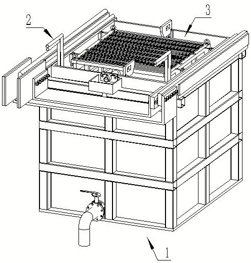
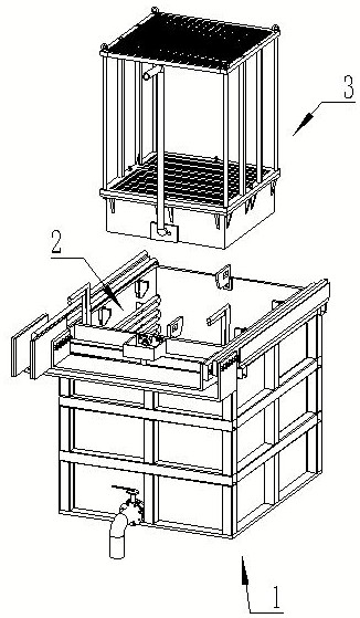
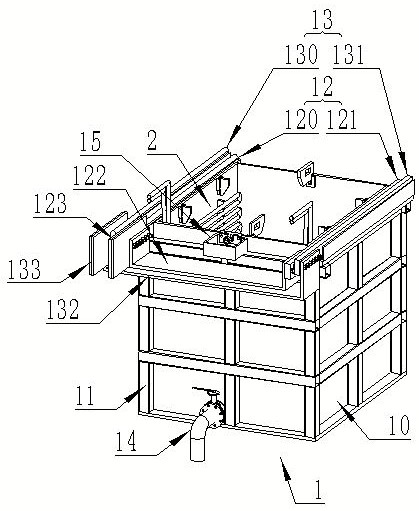
[0051] In order to make the purposes, technical solutions and advantages of the embodiments of the application more clear, the following will combine the Figure 1~13 , clearly and completely describe the technical solutions in the implementation manners of the present application. Obviously, the described implementation manners are part of the implementation manners of the present application, rather than all the implementation manners. Based on the implementation manners in this application, all other implementation manners obtained by persons of ordinary skill in the art without creative efforts fall within the scope of protection of this application. Accordingly, the following detailed description of the embodiments of the application, provided in the accompanying drawings, is not intended to limit the scope of the claimed application, but merely represents selected embodiments of the application. In the description of the present application, it should be understood that ...


PUM


Abstract

The invention discloses an electrolytic bath and an electrolysis device using same, and relates to the technical field of electrolysis equipment. The electrolytic bath comprises an electrolytic bath body, a cooling pipe is fixedly arranged on the inner wall of the electrolytic bath body, an anode plate conductive device and a cathode plate conductive device are fixedly arranged at the two ends of the upper face of the electrolytic bath body correspondingly, the anode plate conductive device is connected with a power supply anode, and the cathode plate conductive device is connected with a power supply cathode. As the anode plate conductive device and the cathode plate conductive device are respectively arranged on two sides of the upper surface of the electrolytic bath body, two-way power supply can be realized simultaneously, so that contact area of polar plates and the conductive devices can be increased to reduce the resistance and increase the current, and poor contact of the polar plates is avoided. According to the electrolysis device, through specially-made anode plates and cathode plates with arc-shaped contact grooves at one ends, the contact area can be increased, the working current can be improved, and the phenomena of heating and poor contact can be reduced, so that the electrolysis efficiency can be greatly improved.

Description

technical field [0001] The present application relates to the technical field of electrolysis equipment, in particular to an electrolysis cell and an electrolysis device using the electrolysis cell. Background technique [0002] At present, the electrolytic manganese industry uses small electrolytic cells. The width of the electrolytic cell is 980mm, the height is 1020mm, and the length is between 2000mm and 5000mm. Under the same production capacity, the number of small electrolytic cells required is large, the number of plates is large, and the operating current of the single plate Small, high labor cost, high operating cost, very unfavorable for automatic operation. The false bottom of the small electrolytic cell is welded in the cell and becomes a whole with the electrolytic cell, which is difficult to clean, maintain, and recycle the electrolyte. Contents of the invention [0003] In order to solve the above problems, one of the present application provides an electr...

Claims


Application Information

Patent Timeline
Patent Type & Authority Applications(China)
IPC IPC(8): C25C1/10C25C3/30C25C7/00C25C7/02C25C7/04C25C7/06
CPCC25C1/10C25C3/30C25C7/02C25C7/00C25C7/04C25C7/06
Inventor 詹海青韦勇明唐靖葵陈发明闭伟宁农富钧杨勇魏汉可陈升茂农杰卜芳芳
Owner DAXIN MANGANESE MINE BRANCH OF CITIC DAMENG MINING IND
Learn More