Laboratory catalytic cracking reactor

A catalytic cracking and reactor technology, applied in the direction of catalytic cracking, cracking, chemical instruments and methods, etc., can solve the problems of large influence of field distribution, inability to accurately reflect the reaction performance of catalysts, complex components, etc.

Active Publication Date: 2021-11-30
PETROCHINA CO LTD
View PDF13 Cites 1 Cited by
  • Summary
  • Abstract
  • Description
  • Claims
  • Application Information

AI Technical Summary

Problems solved by technology

[0009] In summary, the prior art laboratory catalytic cracking reactor has uneven gas distribution in the reactor, complex internal components for improving gas distribution, and easy to cause coking and Affect the final product distribution
At the same time, there are problems that the change of operating conditions has a great influence on the fluidization state and field distribution inside the reactor, and the regularity and repeatability of product distribution and changes in operating conditions are poor. It is not suitable for catalytic cracking reactions of various raw materials and conditions, and cannot accurately react catalysts Response performance

Method used


Image

  • Laboratory catalytic cracking reactor
  • Laboratory catalytic cracking reactor
  • Laboratory catalytic cracking reactor

Examples


Embodiment 1

[0046] This example is used to illustrate the effect of the laboratory catalytic cracking reactor distribution plate and its fluidization pipe provided by the present invention on improving catalyst distribution.

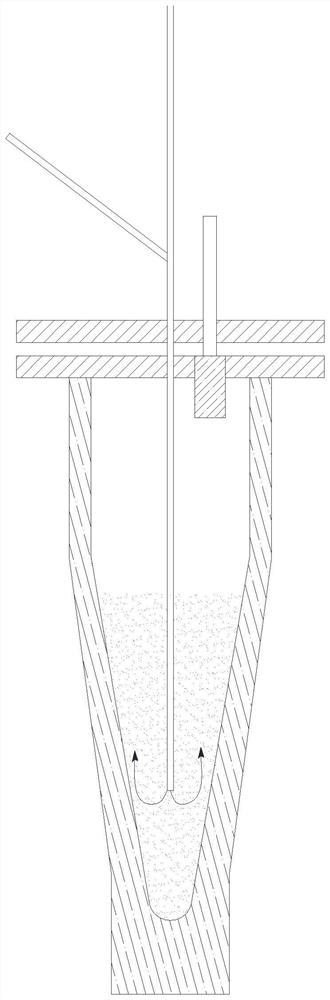
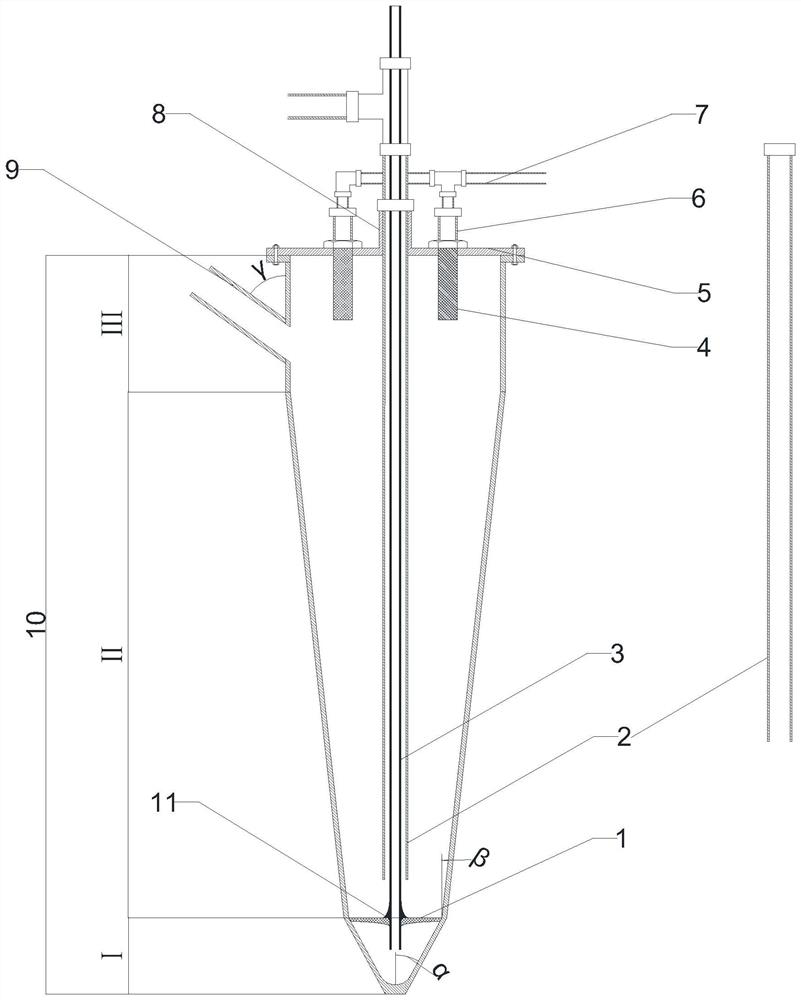
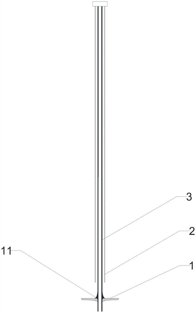
[0047] according to figure 2 The reactor configuration shown in the preparation laboratory catalytic cracking reactor, the distribution plate 1 is at the junction of the reaction section II and the pre-distribution section I, the center of the distribution plate 1 is thick, the edge is thin, the upper surface is flat, the distribution plate 1 The thickness gradually decreases along the track of the elliptical arc with the increase of the radius, and the center of the distribution plate 1 is provided with a cylindrical central hole. The distribution plate 1 adopts alumina ceramics with a porosity of 40%; the reactor adopts the feeding method of top feeding, and the raw material injection pipe 2 enters the reaction section II of the reactor from the top of the reacto...

Embodiment 2

[0050] This example is used to illustrate the effect of adjusting the reaction contact time by changing the height of the feed pipe in the laboratory catalytic cracking reactor provided by the present invention.

[0051] according to figure 2 The shown reactor configuration prepares laboratory catalytic cracking reactor, compares with embodiment 1, and the difference of embodiment 2 is that the length of raw material injection pipe 2 is 80% of the length of embodiment 1 raw material injection pipe, to reduce reaction time . The catalytic cracking reaction was carried out under the same conditions as in Comparative Example 1, and the analysis results are shown in Table 3.

Embodiment 3

[0053] This example is used to illustrate the effect of adjusting the reaction contact time by changing the height of the feed pipe in the laboratory catalytic cracking reactor provided by the present invention.

[0054] according to figure 2 The shown reactor configuration prepares laboratory catalytic cracking reactor, compared with embodiment 1, the difference of embodiment 3 is that the length of raw material injection pipe 2 is 130% of the length of embodiment 1 raw material injection pipe, to increase the reaction time . The catalytic cracking reaction was carried out under the same conditions as in Comparative Example 1, and the analysis results are shown in Table 3.

[0055] Table 1

[0056] project data Density(20℃)(kg·m -3 )

900.8 Distillation range (℃) initial boiling point 213 10% 343 30% 387 50% 483 Carbon residue mass fraction (%) 4.74 Total sulfur mass fraction (%) 0.16

[0057] Table 2

[00...


PUM


Abstract

The invention relates to a laboratory catalytic cracking reactor which comprises a top sealing structure, a reactor body, a product outlet pipe, a filter pipe, a top fluidization pipe, a catalyst loading and unloading port, a raw material injection pipe and a distribution plate. The reactor body comprises a settling section, a reaction section and a pre-distribution section; the distribution plate is positioned at the joint of the pre-distribution section and the reaction section; the raw material injection pipe enters the reaction section from the top sealing structure along the central axis; the top fluidization pipe penetrates through the inside of the raw material injection pipe, penetrates through the distribution plate, is fixed under the action of a positioner at the lower part of the top fluidization pipe, and enters the pre-distribution section; the catalyst loading and unloading port is positioned on the side wall of the settling section. The laboratory catalytic cracking reactor has the characteristics of stable bed linear velocity, full oil agent contact, and accurate control of reaction temperature and oil agent contact time.

Description

technical field [0001] The invention relates to a laboratory catalytic cracking reaction device. Background technique [0002] Catalytic cracking is a technology that cracks petroleum hydrocarbons in the presence of catalysts to produce low-carbon olefins. Due to the advantages of wide source of raw materials, easy adjustment of olefin product structure, low energy consumption and less carbon dioxide emissions, catalytic cracking technology has made great progress in recent years. a faster development. In particular, with the diversification of raw materials, making full use of resources, flexibly adjusting products, and improving the economic efficiency of refineries are the main directions of catalytic cracking technology. The process development around this technology, the development of catalysts, or the screening and evaluation of different feedstock oils and catalysts are all inseparable from small laboratory evaluation devices. [0003] At present, the experimental ...

Claims


Application Information

Patent Timeline
Patent Type & Authority Applications(China)
IPC IPC(8): C10G11/18C10G11/05B01J8/24B01J4/00
CPCC10G11/18C10G11/05B01J8/24B01J4/001
Inventor 杜晓辉任世宏刘璞生刘超伟孙书红曹兰花马艳萍刘涛王智峰廖翼涛樊江涛
Owner PETROCHINA CO LTD
Why Eureka
Try Eureka