A fixed fluidized bed reactor and its application

A technology of fixed fluidized bed and reactor, applied in chemical instruments and methods, cracking, catalytic cracking, etc., can solve problems such as uneven distribution of catalyst, insufficient contact of oil agent, affecting product distribution, etc., to improve product distribution, Sufficient oil contact and stable bed velocity

Active Publication Date: 2016-03-02
CHINA PETROLEUM & CHEM CORP +1
View PDF10 Cites 0 Cited by
  • Summary
  • Abstract
  • Description
  • Claims
  • Application Information

AI Technical Summary

Problems solved by technology

[0008] In summary, the fixed fluidized bed reactors in the prior art are mainly aimed at the conventional catalytic cracking and catalytic cracking of heavy oils, because the catalytic cracking reactions of light oils such as naphtha have high reaction temperature and low catalyst-to-oil ratio. Large, high oil and gas linear velocity, prolific gas production, etc., but when the above-mentioned fixed fluidized bed reactor is used for catalytic cracking, the catalyst distribution in the bed is not uniform under high temperature reaction conditions, and the oil agent is not in sufficient contact, which will affect The final product distribution, so the fixed fluidized bed reactor of the prior art is not suitable for the catalytic cracking reaction temperature of light oil products such as naphtha, high reaction temperature, large agent-oil ratio, high oil-gas linear velocity, prolific gas production, etc. special response needs

Method used


Image

  • A fixed fluidized bed reactor and its application
  • A fixed fluidized bed reactor and its application
  • A fixed fluidized bed reactor and its application

Examples


Embodiment 1

[0065] This example is used to illustrate the fixed fluidized bed reactor provided by the present invention and its application.

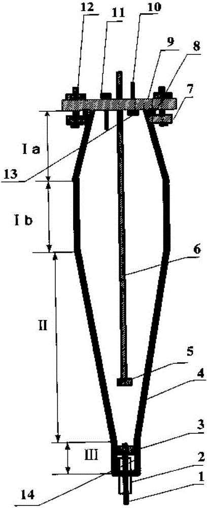
[0066] according to Figure 4 The reactor configuration shown is a fixed fluidized bed reactor, and the reaction section II includes the first reaction section II-1 and the second reaction section II-2 from top to bottom, and the cross-sectional area of ​​the lower end of the settling section I is the same as The cross-sectional area of ​​the upper end of the first reaction section II-1 is equal, the cross-sectional area of ​​the lower end of the first reaction section II-1 is equal to the cross-sectional area of ​​the upper end of the second reaction section II-2, and the lower end of the second reaction section II-2 The cross-sectional area is equal to the cross-sectional area of ​​the upper end of the oil agent initial contact section III, and the cross-sectional area of ​​the first reaction section II-1 gradually increases from top to bottom, a...

Embodiment 2

[0086] This example is used to illustrate the fixed fluidized bed reactor provided by the present invention and its application.

[0087] According to the method of embodiment 1, adopt the fixed fluidized bed reactor described in this embodiment, the straight-run naphtha whose raw material properties are as shown in table 1 is catalyzed under the effect of catalyst properties as shown in table 2 Cracking reaction, and analysis of reaction products, operating conditions and product analysis results are shown in Table 4.

[0088] The difference is that the size parameters of each section of the fixed fluidized bed reactor used in this example are different, and the first reaction section II-1 and the second reaction section II-2 of the fixed fluidized bed reactor used in this example are both It is in the shape of a truncated cone, wherein the angle α of the first reaction section II-1 of the truncated shape is 41°; the angle β of the second reaction section II-2 of the truncate...

Embodiment 3

[0099] This example is used to illustrate the fixed fluidized bed reactor provided by the present invention and its application.

[0100] According to the method of embodiment 1, adopt the fixed fluidized bed reactor described in embodiment 1 to carry out catalytic cracking under the effect of the catalyzer of catalyst property as shown in table 2 to the straight-run naphtha whose raw material properties are as shown in table 1 Reaction, the difference is that only the cone angle and the aspect ratio of the oil agent initial contact section III are changed, the cone angle of the oil agent contact section III is 30°, and the aspect ratio of the oil agent initial contact section III is 1.87: 1, and the reaction product is analyzed, operating conditions and product analysis results are shown in Table 5.

[0101] table 5

[0102]

[0103] From the results in Table 5 above, it can be seen that under the condition that other conditions remain unchanged, only the cone angle of th...


PUM

PropertyMeasurementUnit
pore sizeaaaaaaaaaa
pore sizeaaaaaaaaaa
pore sizeaaaaaaaaaa

Abstract

The invention discloses a fixed fluidized bed reactor and an application thereof. The reactor comprises a top sealing structure and a reactor main body; an outlet pipe (8) and a material feeding pipe (1) are communicated with the reactor; the reactor main body comprises, from up to down, a settling section (I), a first reaction section (II-1), a second reaction section (II-2), and an oil agent initial contact section (III); the cross-sectional area of the lower end of the settling section (I) is equal to the cross-sectional area of the upper end of the first reaction section (II-1); the cross-sectional area of the lower end of the first reaction section (II-1) is equal to the cross-sectional area of the upper end of the second reaction section (II-2); the cross-sectional area of the lower end of the second reaction section (II-2) is equal to the cross-sectional area of the upper end of the oil agent initial contact section (III); the cross-sectional area of the first reaction section (II-1) increases gradually from up to down; and the cross-sectional area of the second reaction section (II-2) decreases gradually from up to down. When used in catalytic cracking of light oil such as naphtha and the like, the fixed fluidized bed reactor provided by the invention has the advantages of stable bed layer linear speed, complete oil agent contact, and the like, and is beneficial to product distribution improvement.

Description

technical field [0001] The invention relates to a fixed fluidized bed reactor and its application. Background technique [0002] Catalytic cracking is a technology that cracks petroleum hydrocarbons in the presence of catalysts to produce low-carbon olefins. Due to the advantages of wide source of raw materials, easy adjustment of olefin product structure, low energy consumption and less carbon dioxide emissions, catalytic cracking technology has made great progress in recent years. a faster development. Especially for light oil products such as naphtha catalytic cracking technology is an important technology to optimize the utilization of naphtha resources and improve the economic benefits of refineries. The process development around this technology, the development of catalysts, or the screening of different feedstock oils and catalysts The evaluation is inseparable from the small evaluation device in the laboratory. [0003] At present, the experimental devices used in...

Claims


Application Information

Patent Timeline
Patent Type & Authority Patents(China)
IPC IPC(8): B01J8/24C10G11/18C10G49/16
Inventor 任世宏毛安国魏晓丽
Owner CHINA PETROLEUM & CHEM CORP
Why Eureka
Try Eureka