Cutting equipment for building boards
A technology for building boards and equipment, which is applied in the field of board processing, can solve the problems of discontinuous cutting process and low cutting efficiency of boards, and achieve the effect of continuous cutting process and improved cutting efficiency
- Summary
- Abstract
- Description
- Claims
- Application Information
AI Technical Summary
Problems solved by technology
Method used
Image

Examples
Embodiment 1
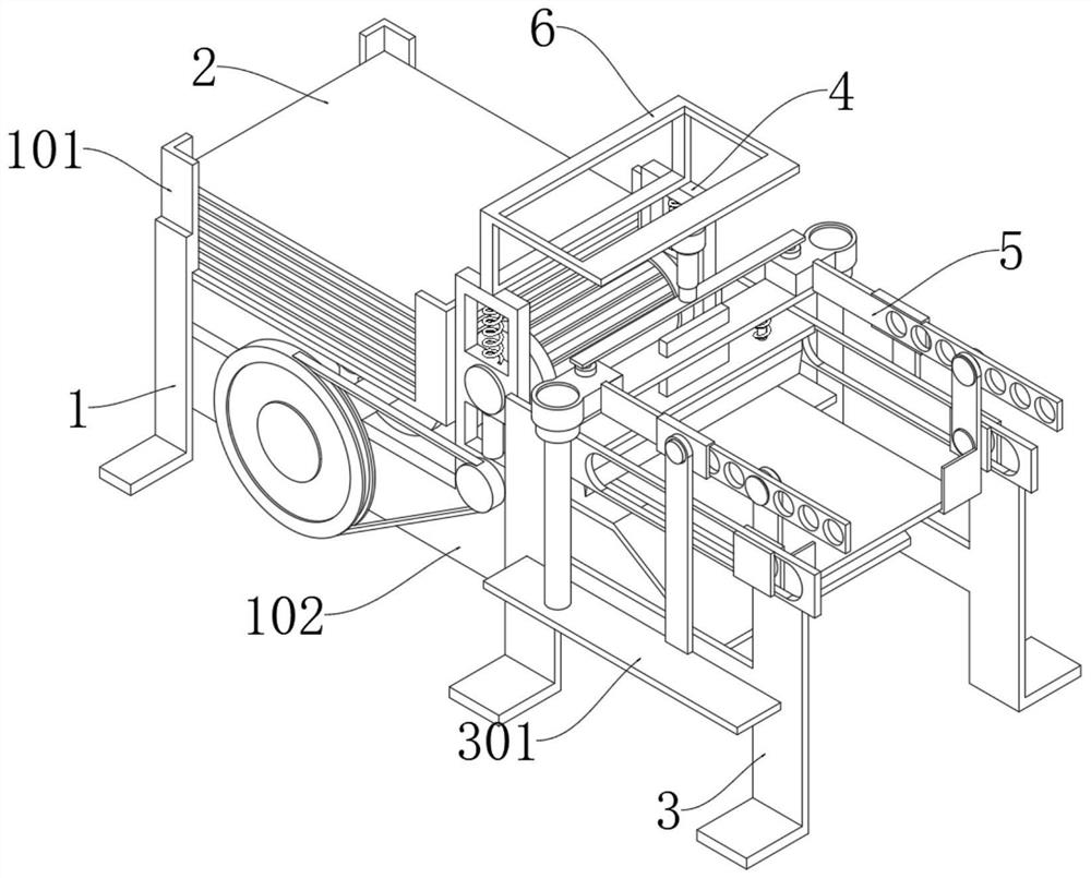
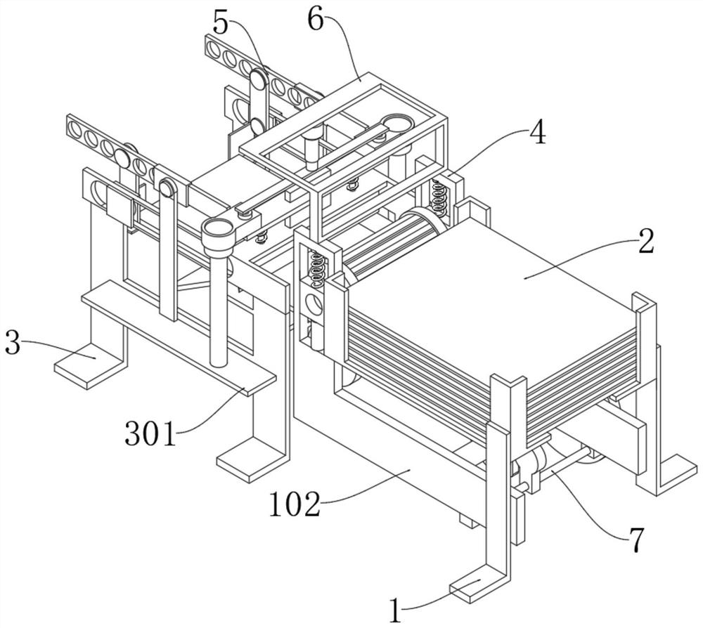
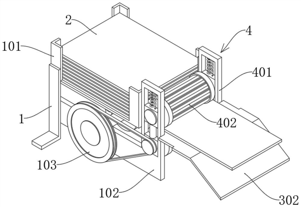
[0034] see Figure 1-5 , a cutting device for building boards, comprising a front bracket 3 and a rear bracket 1, the rear bracket 1 is fixedly connected with a loading rack 101, inside the loading rack 101 there are boards 2 of corresponding sizes neatly stacked; the bottom of the loading rack 101 is arranged There is a transmission frame 102, and the transmission frame 102 is fixedly connected to the center of the rear support 1, and the center of the front side of the transmission frame 102 is fixedly connected to a blanking platform 302, and the front side of the upper end of the transmission frame 102 is fixedly connected to a feeding mechanism 4, and the upper side of the feeding mechanism 4 The installation frame 6 is fixedly connected; the front end of the feeding mechanism 4 is provided with a cut-off assembly 5, the cut-off assembly 5 is fixedly connected to the front bracket 3, and a continuous feed assembly 7 is arranged between the transmission frames 102;
[0035...
Embodiment 2
[0040] see Figure 6-8 , based on Example 1, the difference is that:
[0041] The cut-off assembly 5 includes two snapping plates 501, the snapping plates 501 are L-shaped plates, and the two snapping plates 501 match the two corners on the same side of the plate 2; the snapping plates 501 are fixedly connected to the lower end side of the connecting rod 510, connected The rear side of the lower end of the rod 510 is rotatably connected with a slider 511, the slider 511 is slidably connected in the sliding groove 507 of the track plate 502, and the track plate 502 is fixedly connected to the upper end of the front bracket 301;
[0042] The upper end of the connecting rod 510 is movably connected with a nut assembly, and the connecting rod 510 is movably connected to the shift plate 505 through the nut assembly. Connection; the outer side of the gear plate 505 is movably connected with a sliding sleeve block 509, the rear side of the sliding sleeve block 509 is connected to th...
Embodiment 3
[0047] see Figure 9 , based on Embodiment 1 and 2, the difference is that:
[0048] The continuous feeding assembly 7 includes a special-shaped wheel 701, which is fixedly connected to the center of the axis of the transmission wheel 103, and one side of the special-shaped wheel 701 is in movable contact with an offset wheel 703, and the offset wheel 703 is fixedly connected to the middle and lower part of the swing rod 702 The lower end of the swing rod 702 is rotatably connected to the rotating shaft, and the two ends of the rotating shaft are fixedly connected between the two drive frames 102, and the upper end of the swing rod 702 is rotatably connected to a feeder plate 704; the upper end of the feeder plate 704 is fixedly connected to an extrusion Block 705, the upper side of the feeding plate 704 is in contact with the bottom surface of the plate 2, and one side of the upper end of the swing rod 702 is movably connected to one side of the connecting plate 707 through a...
PUM
 Abstract
Description
Claims
Application Information
 - Generate Ideas
- Intellectual Property
- Life Sciences
- Materials
- Tech Scout
- Unparalleled Data Quality
- Higher Quality Content
- 60% Fewer Hallucinations
Browse by: Latest US Patents, China's latest patents, Technical Efficacy Thesaurus, Application Domain, Technology Topic, Popular Technical Reports.
© 2025 PatSnap. All rights reserved.Legal|Privacy policy|Modern Slavery Act Transparency Statement|Sitemap|About US| Contact US: help@patsnap.com