
Milling process-oriented carbon emission chemical calculation method and system

A carbon emission and milling technology, applied in the field of carbon emission quantification calculation method and system, to achieve the effect of accurate calculation results

Pending Publication Date: 2021-11-26
XI AN JIAOTONG UNIV
View PDF0 Cites 0 Cited by
  • Summary
  • Abstract
  • Description
  • Claims
  • Application Information

AI Technical Summary

Problems solved by technology

However, considering the characteristics of multi-edge interrupted cutting in milling, there is still a lack of a calculation method for energy consumption and carbon emissions suitable for milling.
Therefore, there is still a gap between the existing energy consumption model and carbon emission model and the assessment of carbon emission in the milling process, and further research is needed

Method used


Image

  • Milling process-oriented carbon emission chemical calculation method and system
  • Milling process-oriented carbon emission chemical calculation method and system
  • Milling process-oriented carbon emission chemical calculation method and system

Examples


preparation example Construction

[0088] Preparation of workpiece materials Carbon emissions CE pchip Calculated as follows:

[0089] CE pchip =ΔV×ρ×EF pchip

[0090] where ΔV is the volume of workpiece material removed / m 3 ; ρ is the density of the workpiece material / kg m -3 ;EF pchip is the carbon emission factor of workpiece material preparation / kgCO 2 kg -1 .

[0091] (2) Carbon emissions from tool preparation

[0092] Preparation of knives carbon emissions CE ptool Calculated as follows:

[0093]

[0094] Among them, t c is the cutting time / min of the tool under specific cutting conditions; T t is the tool durability / min of the tool under specific cutting conditions; N is the number of times the tool can be sharpened; m t is the mass of the tool / g; EF ptool is the carbon emission factor of tool production / kgCO 2 kg -1 .

[0095] Among them, the tool life of each machining is estimated by the Taylor tool life equation as follows:

[0096]

[0097] Among them, C V ,K V ,q V ,y V ...

Embodiment

[0241] The technical solutions of the present invention will be described below in conjunction with specific examples.

[0242] Collect the idling power and standby power data of the machine tool spindle with increasing gradient, and compare the power data to obtain the net power of the machine tool spindle idling at different speeds. In order to ensure the accuracy of the experiment, 20 sets of power data were collected under each set of experimental parameters to obtain the average value. The obtained experimental data are shown in Table 1.

[0243] Table 1 VDL-850A spindle speed and net power comparison table

[0244]

[0245] From the experimental data, it can be seen that the rotational power of the spindle increases with the increase of the rotational speed in the form of a piecewise function, which is consistent with the established model of the rotational power of the spindle. Therefore, the collected spindle power data is grouped and processed using IBM SPSS Statist...


PUM


Abstract

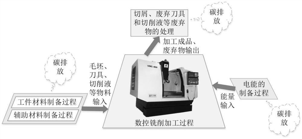
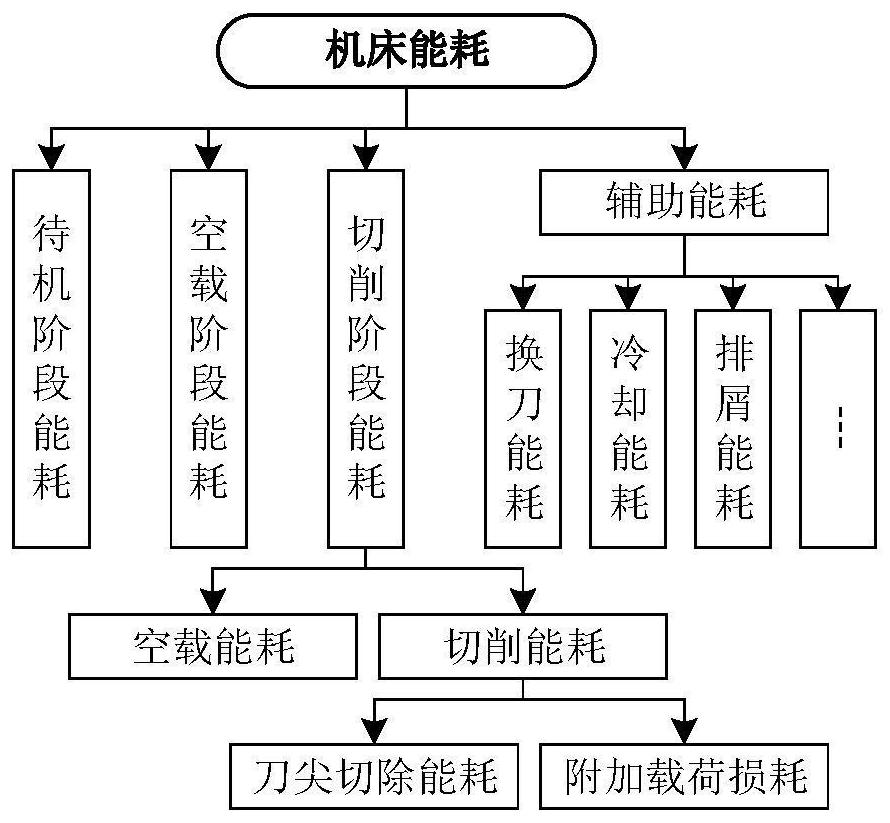
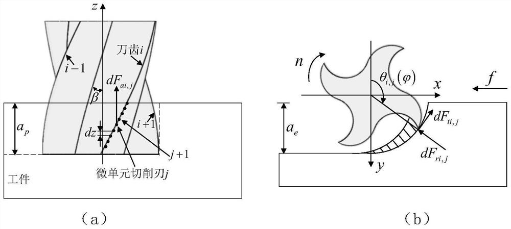
The invention discloses a milling process-oriented carbon emission chemical calculation method and system. The method comprises the following steps: determining a total carbon emission boundary in a numerical control milling process; determining total carbon emission according to a total carbon emission boundary, and calculating material carbon and waste carbon by utilizing a material carbon and waste carbon evaluation method; establishing a micro-unit cutting force calculation model, constructing a milling machining cutting power calculation model through numerical integration derivation, and obtaining cutting power including average tool nose cutting power and machine tool additional load loss power in unit time through calculation; establishing a machine tool energy consumption model including no-load energy consumption, cutting energy consumption and auxiliary energy consumption, determining machine tool energy consumption according to the machine tool energy consumption model, and obtaining carbon emission generated by electric energy consumed by the numerical control machine tool in the numerical control milling machining process in the preparation process through calculation; and realizing carbon emission chemical calculation in the numerical control milling process by combining material carbon, waste carbon and energy carbon. Carbon emission quantitative calculation support is provided for follow-up cutter path and cutting parameter optimization.

Description

technical field [0001] The invention belongs to the technical field of low-carbon manufacturing and intelligent manufacturing, and in particular relates to a carbon emission quantification calculation method and system for milling process. Background technique [0002] Generally, electrical energy is used as the main energy source of machine tools in machining, and electrical energy is mainly provided by carbon-based fuels. Therefore, the energy consumption of machining processes is closely related to the carbon emissions generated. Based on this, most scholars at home and abroad start from the perspective of machine tool energy consumption when conducting research on carbon emissions in machining processes. [0003] The team of Professor Verl of the University of Stuttgart in Germany analyzed the energy consumption characteristics of the machining process and found that the energy consumption of the machine tool is different in different stages such as startup, no-load, pro...

Claims


Application Information

Patent Timeline
IPC IPC(8): G06F30/20G06F111/10
CPCG06F30/20G06F2111/10
Inventor 张超周光辉门松辰张俊杰
Owner XI AN JIAOTONG UNIV
Learn More