
A bagged material handling and conveying device

A conveying device and material technology, which is applied in the direction of transportation and packaging, conveyors, conveyor objects, etc., can solve problems such as difficult to meet the needs of bagged material handling and delivery, bagged material delivery, packaging bag scratches, etc., to improve handling Speed, reduce concentrated force, reduce the effect of damage problems

Active Publication Date: 2022-05-24
SHANDONG UNIV
View PDF0 Cites 0 Cited by
  • Summary
  • Abstract
  • Description
  • Claims
  • Application Information

AI Technical Summary

Problems solved by technology

[0003] Different forms of materials need to be equipped with different feeding equipment. For some solid materials, the feeding can be realized by clamping and lifting equipment. For bagged materials, since the appearance is a soft packaging bag, it can be loaded by clamping and other rigid matching structures. The material equipment is easy to cause scratches to the packaging bags, so the lifting equipment is usually used to carry and load the materials; for the stacked bagged materials, the lifting equipment is lifted from the bottom of the materials, and multiple bags of materials are carried out at the same time each time. The bagged materials cannot be conveyed one by one, and the bagged materials need to be redispersed on the conveyor belt; some of the bagged materials are loaded with vacuum suction cups, and the suction cups are used to absorb the surface of the packaging bags and carry the materials However, during the vertical lifting process, the position of the suction cup absorbing the packaging bag is prone to concentrated force, causing damage to the packaging bag, and it is difficult to meet the handling and transportation needs of the bagged materials.

Method used


Image

  • A bagged material handling and conveying device
  • A bagged material handling and conveying device
  • A bagged material handling and conveying device

Examples


Embodiment 1

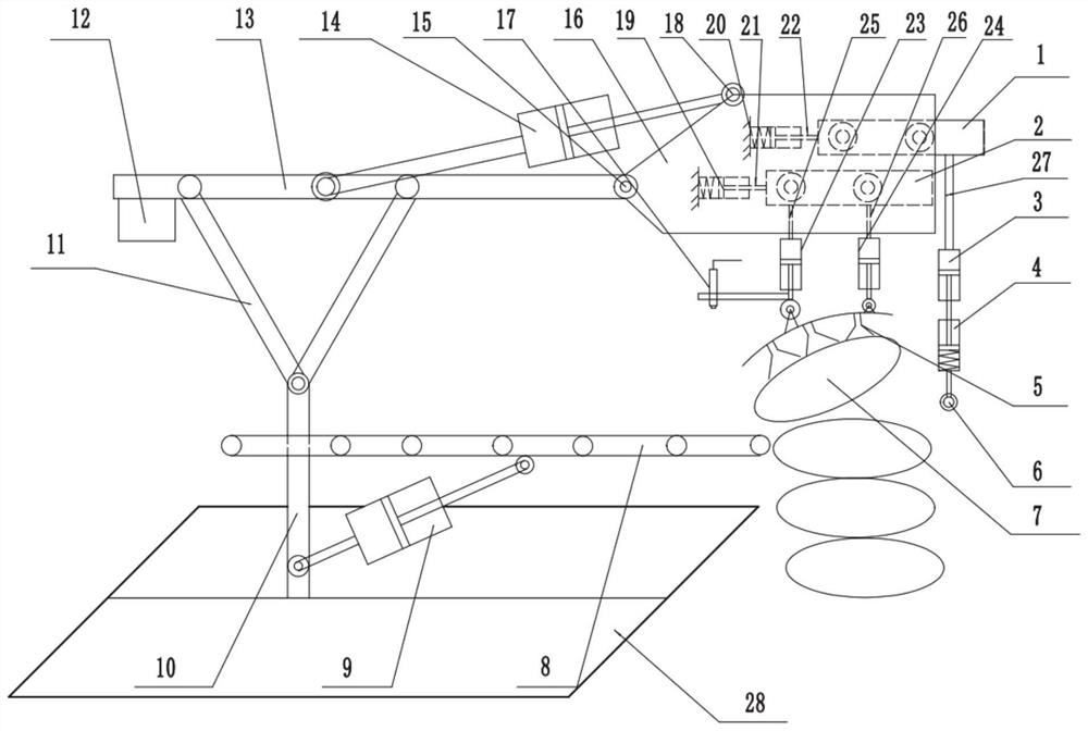
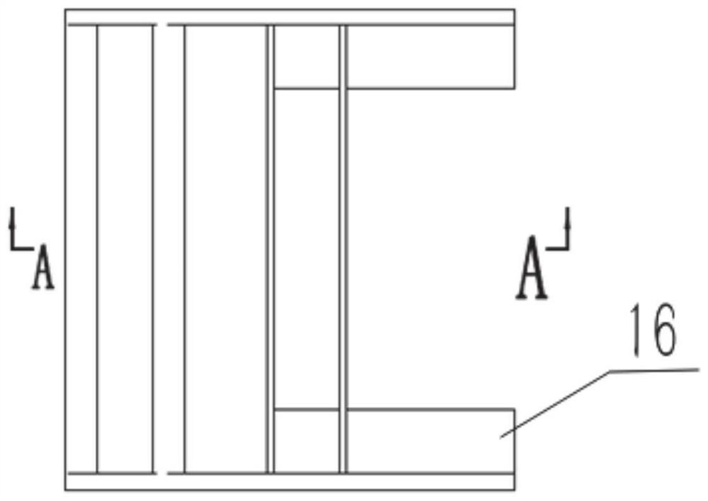
[0030] In a typical embodiment of the present invention, as Figure 1-Figure 5 As shown, a bagged material handling and conveying device is proposed.

[0031] Aiming at the problem that the bagged material 7 is inconvenient to be transported, loaded and transported, and the bagged material 7 is easily damaged, a bagged material 7 handling and conveying device is provided, which uses multiple suction cups to form a suction cup assembly 5, and grabs the bagged material 7 on the suction cups. The suction cup maintains a large contact area with the bagged material 7, reducing the concentrated force at the adsorption position, thereby reducing the damage of the bagged material 7 during the handling process and improving the material handling speed.

[0032] The bagged material 7 handling and conveying device mainly includes a mobile base 28, a mechanical arm, a conveyor belt 8 and a handling structure. The mechanical arm is installed on the mobile base 28, and changes its position ...


PUM


Abstract

The invention provides a bagged material handling and conveying device; it relates to the field of material transfer equipment, including a conveyor belt, a mechanical arm and a handling structure. The handling structure includes a bearing bracket, a suction cup assembly, and a telescopic assembly. One end of the telescopic assembly is connected through a first reciprocating movement pair. The bearing bracket, the other end is connected to the suction cup assembly and the suction cup assembly is suspended under the bearing bracket. The telescopic assembly can be stretched to adjust the suction surface of the suction cup assembly and the vertical surface to form a set angle; the bearing bracket is hinged at the end of the mechanical arm, and the conveyor belt is connected. The mechanical arm and one end of the conveyor belt are located under the supporting bracket. In view of the current inconvenience of bagged material handling and feeding, which may easily lead to damage to the bagged materials, the suction cup assembly is composed of multiple suction cups, which form a tilted state when the suction cup grabs the bagged materials. The suction cup maintains a large contact area with the bagged materials, reducing the concentrated force at the suction position, thereby reducing the damage of the bagged materials during the handling process and improving the handling speed of the materials.

Description

technical field [0001] The invention relates to the field of material transfer equipment, in particular to a bagged material handling and conveying device. Background technique [0002] In the automated production workshop, corresponding special equipment is configured for material handling and loading, and materials are transported from the stacking position to the conveyor belt for conveying and loading. [0003] Different forms of materials need to be equipped with different feeding equipment. For some solid materials, the feeding is realized by clamping and lifting equipment. For bagged materials, because the appearance is a soft packaging bag, the clamping and other rigid matching structures are used. The material equipment is easy to cause the bag to be scratched, so the lifting equipment is used to carry the material; for the stacked bagged materials, the lifting equipment lifts from the bottom of the material, and carries out multiple bags of materials at the same ti...

Claims


Application Information

Patent Timeline
Patent Type & Authority Patents(China)
IPC IPC(8): B65G47/91B65G21/12B65G47/74
CPCB65G47/918B65G21/12B65G47/74
Inventor 谢玉东包木鹏王勇
Owner SHANDONG UNIV
Learn More