Remote control drilling and repairing equipment lifting device and application method

A lifting device and equipment technology, applied in the direction of lifting device, mechanical equipment, fluid pressure actuating device, etc., can solve the problems of many hidden dangers and low work efficiency, so as to avoid hidden dangers of personal safety, and solve the discomfort of mind and body. , the effect of easy remote operation

Pending Publication Date: 2021-11-23
PUYANG ZHENGYI HENGYE MACHINERY ELECTRONICS
View PDF0 Cites 0 Cited by
  • Summary
  • Abstract
  • Description
  • Claims
  • Application Information

AI Technical Summary

Problems solved by technology

[0002] The lifting of the original system is composed of two parts: the lifting workbench and the lifting derrick; in the first step, the operator manually controls the derrick next to the derrick to raise the first-level derrick with variable amplitude, and the observer visually observes the action status on the drilling floor and directs; the operator Manually operate next to the derrick to raise the first-stage derrick; the observer visually observes the action status on the drilling floor and commands, and observes until it is in place; in the second step, the operator manually operates next to the derrick to vertically raise the second-stage derrick, and the observer is on the drilling floor Visually observe the action state and direct it in place; the above operations require the operator to manually control the multi-way reversing valve close to the derrick to complete the system action, and at the same time require the observer to visually judge and direct; these technologies have problems of low work efficiency and many safety hazards

Method used


Image

  • Remote control drilling and repairing equipment lifting device and application method
  • Remote control drilling and repairing equipment lifting device and application method
  • Remote control drilling and repairing equipment lifting device and application method

Examples


Embodiment 1

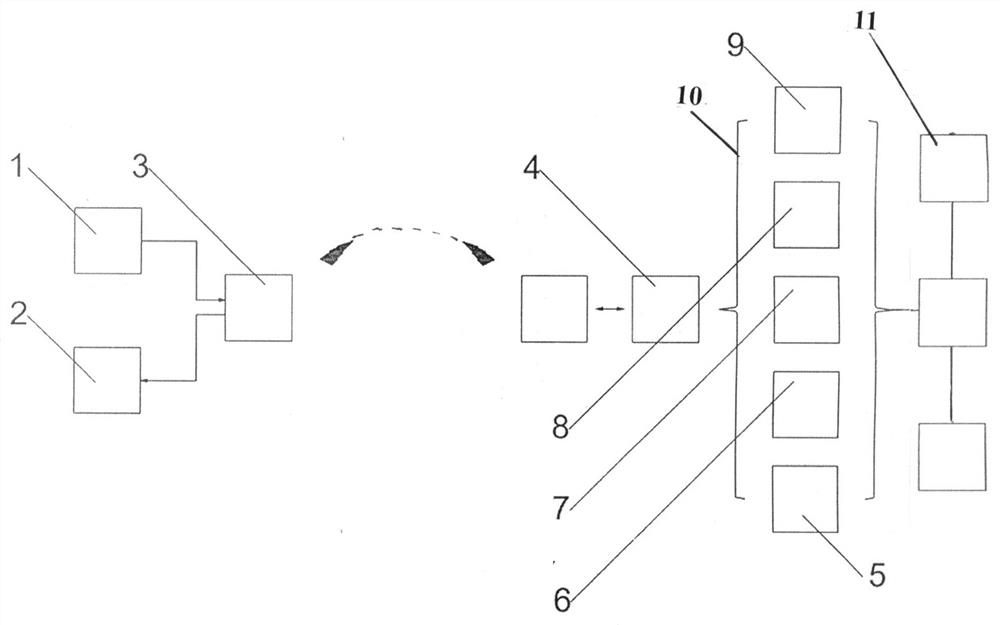
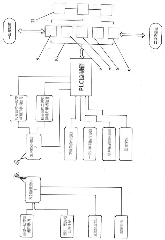
[0013] Embodiment 1. The present invention includes a remote lifting handle 1, a touch display screen 2, a remote transceiver module 3, a PLC control box 4, a high-definition explosion-proof camera 5, a proportional solenoid valve 6, an electromagnetic proportional electro-hydraulic reversing valve 7, and an electromagnetic proportional Relief valve 8, electromagnetic proportional overflow flow valve 9 10, hydraulic integrated block, described remote transceiver module 3 is provided with two pieces, and one end of its remote transceiver module 3 is connected with remote lifting handle 1, touch display screen 2, its The other end of the remote transceiver module 3 is connected to a PLC control box 4; the PLC control box 4 is connected to the hydraulic manifold 10; the hydraulic manifold 10 is connected to the drilling and repairing equipment 11.

Embodiment 2

[0014] Embodiment 2. The hydraulic manifold 10 is connected with a high-definition explosion-proof camera 5 , a proportional solenoid valve 6 , an electromagnetic proportional electro-hydraulic reversing valve 7 , an electromagnetic proportional overflow valve 8 and an electromagnetic proportional overflow flow valve 9 .

Embodiment 3

[0015] Embodiment 3. The hydraulic manifold 10 is connected to the first-stage luffing cylinder and the second-stage luffing cylinder respectively.


PUM


Abstract

The invention discloses a remote control drilling and repairing equipment lifting device and an application method, relates to an equipment lifting technology, and overcomes the defects of other technologies at present. The device comprises a remote lifting handle, a touch display screen, two remote transceiving modules, a PLC (Programmable Logic Controller) control box, a high-definition explosion-proof camera, a proportional electromagnetic valve, an electromagnetic proportional electro-hydraulic directional control valve, an electromagnetic proportional overflow valve, an electromagnetic proportional overflow flow valve and a hydraulic manifold block, wherein one ends of the remote transceiving modules are connected with the lifting handle and the touch display screen, and the other ends of the remote transceiving modules are connected with the PLC control box; the PLC control box is connected with the hydraulic manifold block; and the hydraulic manifold block is connected with drilling and repairing equipment.

Description

technical field [0001] The invention relates to equipment lifting technology, especially a remote control drilling and repairing equipment lifting device and an application method. Background technique [0002] The lifting of the original system is composed of two parts: the lifting workbench and the lifting derrick; in the first step, the operator manually controls the derrick next to the derrick to raise the first-level derrick with variable amplitude, and the observer visually observes the action status on the drilling floor and directs; the operator Manually operate next to the derrick to raise the first-stage derrick; the observer visually observes the action status on the drilling floor and commands, and observes until it is in place; in the second step, the operator manually operates next to the derrick to vertically raise the second-stage derrick, and the observer is on the drilling floor Visually observe the action state and direct it in place; the above operations ...

Claims


Application Information

Patent Timeline
Patent Type & Authority Applications(China)
IPC IPC(8): F15B13/02F15B19/00F15B21/08B66F11/00
CPCF15B13/02F15B19/00F15B21/087F15B21/08B66F11/00
Inventor 段存东史勇
Owner PUYANG ZHENGYI HENGYE MACHINERY ELECTRONICS
Why Eureka
Try Eureka