
Moving magnet type reciprocating linear oscillation motor of low-temperature refrigerator

A low-temperature refrigerator, reciprocating linear technology, applied in the direction of electromechanical devices, magnetic circuit shape/style/structure, reciprocating/oscillating/vibrating magnetic circuit components, etc., can solve unsuitable compressors and refrigerators, magnetic energy products and motors Reduced thrust, increased thickness of the outer stator, etc., to achieve the effect of simplifying the structure of the outer stator, strong magnetic energy, and reducing difficulty

Pending Publication Date: 2021-11-16
上海超立安科技有限责任公司
View PDF0 Cites 0 Cited by
  • Summary
  • Abstract
  • Description
  • Claims
  • Application Information

AI Technical Summary

Problems solved by technology

[0005] The current common moving magnet linear motor-driven compressor adopts a motor structure in which the excitation coil is directly wound on the outer diameter of the outer stator. This not only requires adding a special winding slot, which complicates the winding process, but also makes the outer stator The thickness of the stator increases, the structure is complex, and the processing difficulty becomes greater, thereby increasing the manufacturing cost
In addition, if such a motor structure is adopted, the diameter of the magnetic steel will be reduced, so that the magnetic energy product and the thrust of the motor will be reduced accordingly, which is not suitable for high-power compressors and refrigerators

Method used


Image

  • Moving magnet type reciprocating linear oscillation motor of low-temperature refrigerator
  • Moving magnet type reciprocating linear oscillation motor of low-temperature refrigerator
  • Moving magnet type reciprocating linear oscillation motor of low-temperature refrigerator

Examples


Embodiment Construction

[0026] In the following description, numerous specific details are given in order to provide a more thorough understanding of the present invention. It will be apparent, however, to one skilled in the art that the present invention may be practiced without one or more of these details. In other examples, some technical features known in the art are not described in order to avoid confusion with the present invention.

[0027] In order to thoroughly understand the present invention, detailed steps and detailed structures will be provided in the following description, so as to illustrate the technical solution of the present invention. Preferred embodiments of the present invention are described in detail below, however, the present invention may have other embodiments besides these detailed descriptions.

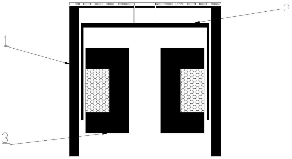
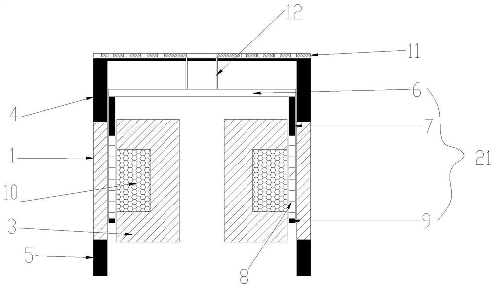
[0028] refer to figure 1 As shown, the present invention provides a moving magnet reciprocating linear oscillating motor for a cryogenic refrigerator. The moving magnet rec...


PUM


Abstract

The invention provides a moving magnet type reciprocating linear oscillation motor of a low-temperature refrigerator, which comprises an inner stator, an outer stator and a rotor, wherein the outer stator is provided with an elastic limiting mechanism; a circle of groove is formed in the outer diameter of the inner stator, and a coil winding is arranged in the groove; the rotor comprises a rotor support and magnetic steel installed on the rotor support, the rotor support is composed of an upper magnetic steel supporting plate, a magnetic steel connecting ring and a lower magnetic steel short gasket, the magnetic steel supporting plate is fixedly installed on the upper end face of the magnetic steel connecting ring, and the magnetic steel supporting plate is connected with the elastic limiting mechanism through a connecting piece. And the magnetic steel is made of a plurality of magnets with ceramic tile structures. The motor has the advantages that 1, the structure of the outer stator is simplified, a special outer stator winding groove is omitted, the cost is reduced, and the winding process is simpler and more convenient; and 2, the coil does not occupy radial space, so that the diameter of the magnetic steel can be made as large as possible, the magnetic energy is stronger, the thrust of the motor is larger, and the motor is suitable for high-power compressors and refrigerators.

Description

technical field [0001] The invention relates to a cryogenic refrigerator, in particular to a moving-magnet reciprocating linear oscillating motor for a cryogenic refrigerator, which is suitable for Stirling refrigerators and pulse tube refrigerators. Background technique [0002] With the advancement of science and technology, low-temperature refrigerators are widely used in military and civilian fields, and reciprocating compressors are used as the driving equipment of refrigerators, and their working performance directly affects the operating power, service life and reliability of refrigerators. [0003] Reciprocating compressors can be divided into rotary motor drive and reciprocating linear oscillating motor drive according to the different motor drive methods. In the early days, compressors driven by rotary motors were often used. The crank-link mechanism was prone to wear, and the structure was complex and the vibration and noise were large, which made the operating ef...

Claims


Application Information

Patent Timeline
Patent Type & Authority Applications(China)
IPC IPC(8): H02K16/00H02K41/02H02K33/00H02K1/12H02K1/16H02K1/34H02K3/48
CPCH02K16/00H02K41/02H02K41/031H02K33/00H02K1/12H02K1/165H02K1/34H02K3/48
Inventor 熊超张安阔方刚
Owner 上海超立安科技有限责任公司
Learn More