
Intelligent reflection surface reflection phase configuration method based on neural network

A reflective surface, neural network technology, applied in baseband systems, baseband system components, digital transmission systems, etc., can solve problems such as difficult applications, intelligent reflective surfaces do not have the ability to receive and analyze signals, and achieve quality improvement and good optimization effects. , the effect of excellent information transmission performance

Pending Publication Date: 2021-11-12
ZHEJIANG LAB +1
View PDF0 Cites 2 Cited by
  • Summary
  • Abstract
  • Description
  • Claims
  • Application Information

AI Technical Summary

Problems solved by technology

In fact, the smart reflective surface does not have the function of receiving and analyzing signals, and it is difficult to accurately estimate the instantaneous channel state information of each channel, so it is difficult to be applied in practical systems

Method used


Image

  • Intelligent reflection surface reflection phase configuration method based on neural network
  • Intelligent reflection surface reflection phase configuration method based on neural network
  • Intelligent reflection surface reflection phase configuration method based on neural network

Examples


Embodiment 1

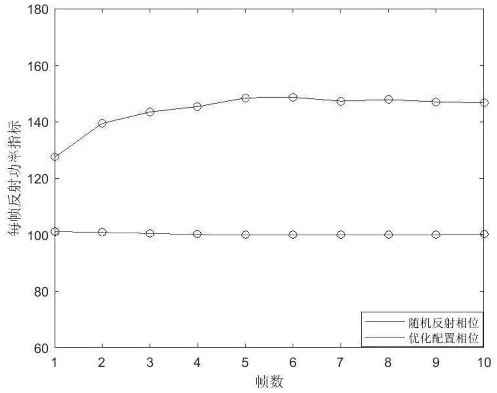
[0073] This embodiment shows how to implement the method for real-time adjustment of intelligent reflective surface-assisted wireless communication reflective phase configuration described in the present invention by using a neural network. In this embodiment, the uplink data transmission scenario is adopted, the number of units of the smart reflective surface is K=64, which is regularly distributed in space, the antenna of the transmitting end is 1, the antenna of the receiving end is 3, h d , h out , h in is a Rayleigh distributed channel, assuming that the channel state information H∈C in each data frame M×N Does not change, the channel state information h after each frame is transmitted d , h out , h in Minor changes occur, the transmitted signal power remains unchanged, 50% of the transmitted energy arrives through the direct path, and 50% reaches through the reflection of the intelligent reflective surface. Each frame contains 32 time slots, among which the first 8 ...

Embodiment 2

[0083] This embodiment shows how to implement the method for real-time adjustment of intelligent reflective surface-assisted wireless communication reflective phase configuration described in the present invention by using a neural network. In this embodiment, the uplink data transmission scenario is adopted, the number of units of the smart reflective surface is K=64, which is regularly distributed in space, the antenna of the transmitting end is 1, the antenna of the receiving end is 3, h d , h out , h in is a Rayleigh distributed channel, assuming that the channel state information H∈C in each data frame M×N Does not change, the channel state information h after each frame is transmitted d , h out , h in Minor changes occur, the transmitted signal power remains unchanged, 50% of the transmitted energy arrives through the direct path, and 50% reaches through the reflection of the intelligent reflective surface. Each frame contains 32 time slots, among which the first 8 ...


PUM


Abstract

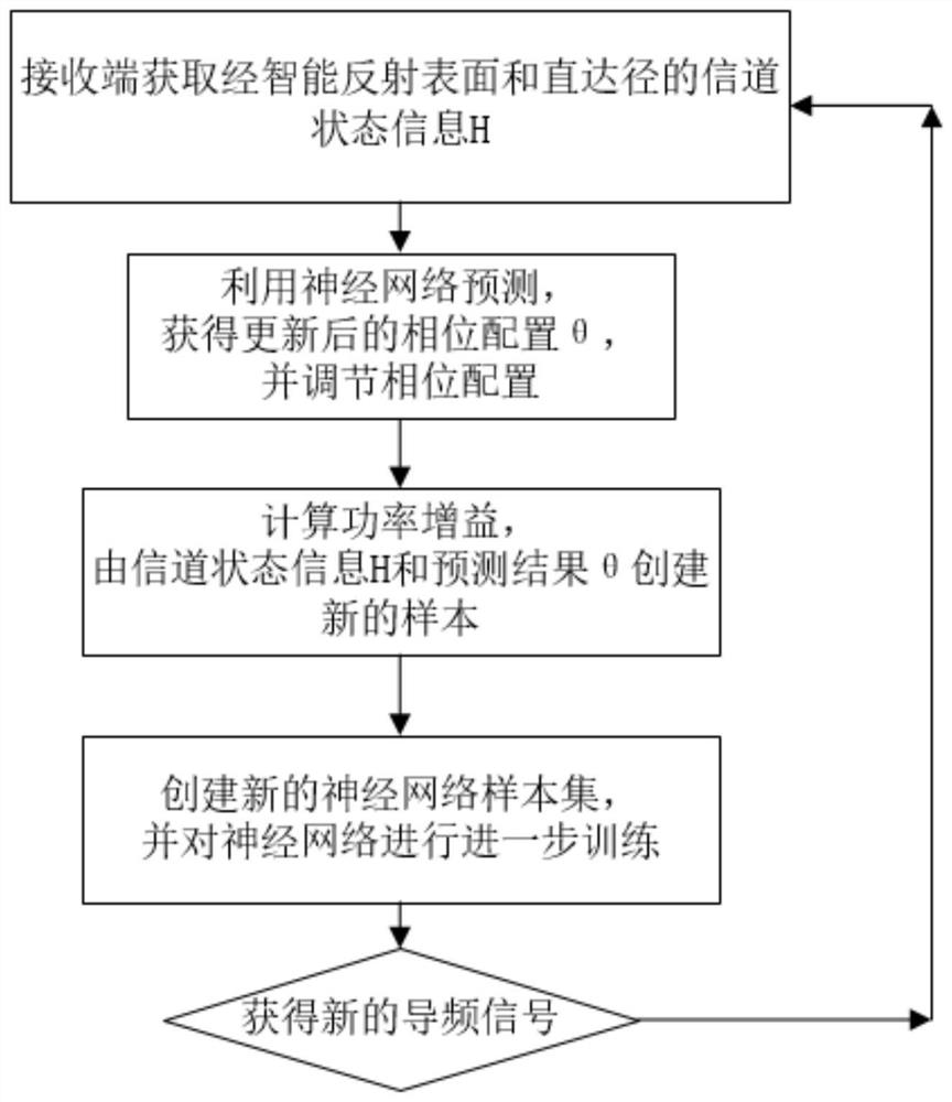
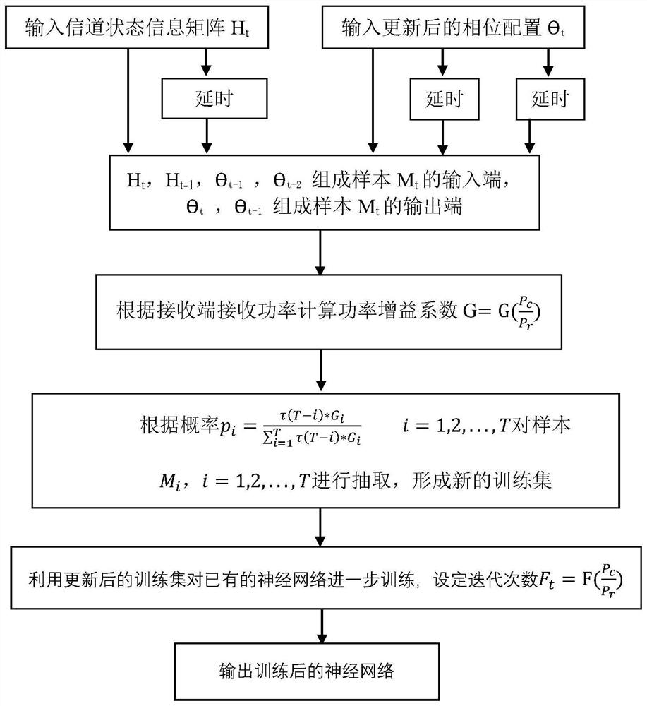
The invention discloses an intelligent reflection surface reflection phase configuration method based on a neural network, and the method comprises the steps that: a pilot signal is transmitted to a receiving end through a transmitting end, and the receiving end is enabled to obtain channel state information; the base station end predicts the optimal reflection phase according to the obtained statistical channel state information and the neural network, controls the intelligent reflection surface through a wired or wireless link, optimizes the reflection phase of a reflection array, updates a neural network data set, continues to train neural network parameters, and when the carrier frequency, the relative spatial position or the wireless transmission environment between the transmitting end and the receiving end of the transmitting end or the receiving end are changed to cause the change of the statistical channel state information, the steps are repeated. According to the method, the reflection phase is configured by using the channel state information, and the optimized intelligent reflection surface optimization phase configuration is quickly predicted by continuously optimizing the neural network model parameters, so that the power of the received signal is optimized.

Description

technical field [0001] The invention relates to a neural network-based intelligent reflective surface phase configuration method, which belongs to the technical field of wireless communication. Background technique [0002] Recently, with the advancement of new artificial electromagnetic materials, smart reflective surfaces have been proposed as a promising low-cost solution to make the propagation environment between transceivers controllable by modifying the propagation environment of wireless communication systems. , so as to realize the optimization of signal transmission. [0003] The intelligent emitting surface is a planar array composed of a large number of passive components. Through the intelligent controller, each element can produce controllable phase offset, amplitude attenuation and other effects independently of the incident electromagnetic wave. By adjusting all the components on the intelligent reflecting surface Phase shifting of the elements, the reflecte...

Claims


Application Information

Patent Timeline
Patent Type & Authority Applications(China)
IPC IPC(8): H04L25/02H04W24/02H04W24/08
CPCH04L25/0228H04L25/0254H04W24/02H04W24/08Y02D30/70
Inventor 党建鲁文韬朱永东郭荣斌张在琛吴亮
Owner ZHEJIANG LAB
Learn More