
Sedimentary facies identification method, device and system

An identification method and sedimentary facies technology, applied in the field of sedimentary facies identification, can solve problems such as inaccurate identification of different sedimentary facies, achieve the effect of improving accuracy and increasing oil and gas production and reserves

Pending Publication Date: 2021-11-12
CHINA PETROLEUM & CHEM CORP +1
View PDF3 Cites 0 Cited by
  • Summary
  • Abstract
  • Description
  • Claims
  • Application Information

AI Technical Summary

Benefits of technology

This technology describes a new way to identify depositional structures such as fault lines or fractures during petroleum exploration. It does this without requiring detailed knowledge about how these structures were formed beforehand because it identifies them based only upon their location within the basin where they are located. By comparing existing data sets obtained under specific conditions (such as temperature) against those already known, we have developed a more accurate technique called Deposit Threatonization Identification System which helps predicting key areas related to hydrocarbon accumulation.

Problems solved by technology

Technologies described include traditional techniques such as open pit mineral prospecting and stratigraphy. However, they have limitations that limit their effectiveness and usefulness across various fields like petroleum exploitation and environmental monitoring. These technical problem addressed by the present inventors involve improving upon existing technics used during field investigations due to challenged areas' lack of knowledge about sedimentation basin structures and associated features.

Method used


Image

  • Sedimentary facies identification method, device and system
  • Sedimentary facies identification method, device and system
  • Sedimentary facies identification method, device and system

Examples


Embodiment 1

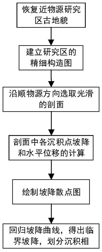
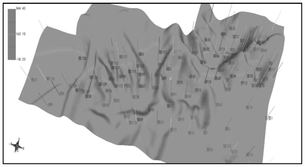
[0038] The main idea of ​​the sedimentary facies identification method proposed in this example is to use the paleogeomorphology restoration map that reflects the geological structure, combined with the principle of different slope angles of different sedimentary facies, to obtain the critical slope angle between different sedimentary facies, and then realize the different sedimentary facies. identification and classification.

[0039] Taking a certain research area W in a certain basin as an example to identify and divide alluvial fan sedimentary facies and fluvial facies sedimentary facies (i.e. braided river sedimentary facies) as an example, the method of the present invention will be described in detail. From the background of historical deposition, alluvial fan deposition The location where the facies develops is closer to the provenance area than the location where the fluvial sedimentary facies develops, and the area where the alluvial fan sedimentary facies is formed n...

Embodiment 2

[0060] The sedimentary facies identification method proposed in this example differs from the sedimentary facies identification method in Example 1 in that the means of paleogeomorphology recovery are different. In this example, the sandstone porosity method, or the mudstone sonic time difference method, or the sedimentation rate method, etc. Thickness restoration method for paleogeomorphology restoration.

[0061] The above paleogeomorphological recovery methods are all existing technologies, and will not be described in detail in this embodiment.


PUM


Abstract

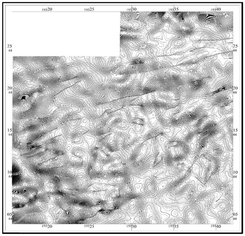
The invention relates to a sedimentary facies identification method, device and system, and belongs to the technical field of oil-gas field development geology. The identification method comprises the following steps: carrying out ancient landform recovery on a research area to obtain an ancient landform map after deposition of the research area; converting the ancient landform map into a vector structure map; selecting a calculation section on the vector structure map along the object source direction; selecting a plurality of deposition points on the calculation profile, including the highest deposition point; obtaining gradient and horizontal displacement of each deposition point relative to the highest deposition point according to the coordinates of each deposition point; performing staged fitting on the gradient and the horizontal displacement of each deposition point relative to the highest deposition point, finding out inflection points between stages, and taking a gradient value at the inflection points as a critical gradient value; and identifying each sedimentary facies according to the critical gradient value. According to the method, the accuracy of sedimentary facies identification is improved, the boundaries between the sedimentary facies can be quantitatively found out through the critical gradient values, and the sedimentary facies region is accurately divided.

Description


Claims


Application Information

Patent Timeline
Owner CHINA PETROLEUM & CHEM CORP
Learn More